Nissan Primera P12. Manual - part 433


  Главная      Nissan     Nissan Primera P12 - Service Manual


поиск по сайту            


содержание   ..  431  432  433  434   ..


Nissan Primera P12. Manual - part 433


EM-78

[YD]

CYLINDER HEAD

CYLINDER HEAD

PFP:11041

On-Vehicle Service

EBS00SO0

CHECKING COMPRESSION PRESSURE

1.

Warm up engine thoroughly. Then, stop it.

2.

Using CONSULT-II, make sure no error codes are indicated for self-diagnosis items. Refer to

EC-44,

"Basic Inspection"

.

Do not disconnect CONSULT-II until the end of this operation; it will be used to check engine rpm and
for error detection at the end of this operation.

3.

Disconnect the negative battery cable.
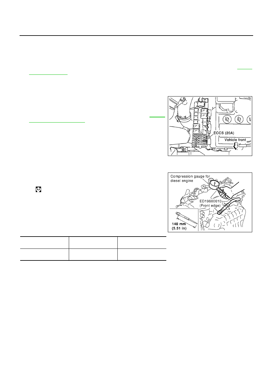
4.

To prevent fuel from being injected during inspection, remove
fuse [ECCS (20A)] from fuse box on the left side of engine com-
partment.

5.

Remove glow plugs from all the cylinders. Refer to

EM-34,

"Removal and Installation"

.

CAUTION:

Before removal, clean the surrounding area to prevent
entry of any foreign materials into the engine.

Carefully remove glow plugs to prevent any damage or
breakage.

Handle with care to avoid applying any shock to glow
plugs.

6.

Install adapter to installation holes of glow plugs and connect
compression gauge for diesel engine.

7.

Connect battery negative terminal.

8.

Set the ignition switch to “START” and crank. When gauge
pointer stabilizes, read compression pressure and engine rpm.
Repeat the above steps for each cylinder.

Always use a fully-charged battery to obtain specified engine
speed.

Unit: kPa (bar, kg/cm

2

, psi)/rpm

When engine rpm is out of the specified range, check the specific gravity of battery liquid. Measure
again under corrected conditions.

If engine rpm exceeds the limit, check valve clearance and combustion chamber components (valves,
valve seats, cylinder head gaskets, piston rings, pistons, cylinder bores, cylinder block upper and lower
surfaces) and measure again.

If compression pressure is low in some cylinders, apply engine oil from glow plug installation hole. Then
check pressure again.

If compression pressure becomes normal after applying oil, piston ring may be worn or damaged.
Check piston ring for malfunction. If any, replace piston ring.

If compression pressure is still low after applying oil, valve may be malfunctioning. Check valve for mal-
function. If contact malfunction is found, replace valve or valve seat.

If compression pressure in adjacent two cylinders is low after applying oil, pressure may be leaking
from gasket. In this case, replace cylinder head gasket.

9.

Complete this operation as follows.

a.

Turn the ignition switch to “OFF”.

b.

Disconnect negative battery cable.

PBIC0738E

: 18 - 21 N·m (1.8 - 2.2 kg-m, 13 - 15 ft-lb)

Standard

Minimum

Difference limit between

cylinders

2,991 (29.99, 30.5, 434)/

200

2,452 (24.52, 25.0, 356)/

200

490 (4.90, 5.0, 71)/200

SEM112G

CYLINDER HEAD

EM-79

[YD]

C

D

E

F

G

H

I

J

K

L

M

A

EM

c.

Install glow plug and install all the parts removed in step 4.

d.

Install fuse [ECCS (20A)].

e.

Connect negative battery cable.

f.

Using CONSULT-II make sure no error code is indicated for items of self-diagnosis.

Removal and Installation

EBS00SO1

CAUTION:

Apply new engine oil to parts marked in illustration before installation.

REMOVAL

1.

Drain engine coolant. Refer to

CO-8, "Changing Engine Coolant"

.

2.

Remove the following parts.

Rocker cover (Refer to

EM-52, "Removal and Installation"

.)

Air cleaner and air duct (Refer to

EM-15, "Removal and Installation"

.)

Vacuum pump (Refer to

EM-35, "Removal and Installation"

.)

Injection tube, spill tube and fuel injector (Refer to

EM-39, "Removal and Installation"

.)

Intake manifold (Refer to

EM-19, "Removal and Installation"

.)

Exhaust manifold and turbocharger (Refer to

EM-23, "Removal and Installation"

.)

Secondary timing chain (Refer to

EM-63, "Removal and Installation"

.)

Camshaft (Refer to

EM-54, "Removal and Installation"

.)

PBIC0946E

1.

Glow plug

2.

Cylinder head assembly

3.

Cylinder head bolt

4.

Gasket

5.

Engine coolant temperature sensor

6.

Gasket

7.

Water outlet

8.

Glow plate

EM-80

[YD]

CYLINDER HEAD

3.

Remove cylinder head assembly.

Loosen and remove mounting bolts in the reverse order
shown in the figure.

Lift up the cylinder head assembly to avoid interference with
dowel pins located between the block and head, and remove
cylinder head assembly.

CAUTION:

Remove glow plug in advance to avoid damage as the tip
of the glow plug projects from the bottom of the cylinder
head, or, place wood blocks beneath both ends of the cyl-
inder head to keep the cylinder bottom from any contact.

For glow plug removal, the following shall be noted.

CAUTION:

To avoid breakage, do not remove glow plug unless necessary.

Perform continuity test with glow plug installed.

Keep glow plug from any impact. (Replace if dropped from a height 10 cm (3.94 in) or higher.)

Do not use air impact wrench.

INSPECTION AFTER REMOVAL
Cylinder Head Bolt Deformation

Using micrometer, measure the outer diameters d1 and d2 of
bolt thread as shown in the figure.

If the necking point can be identified, set it as measuring point
d2.

Calculate the difference between d1 and d2.

If out of the limit, replace cylinder head bolt.

Cylinder Head-to-block Difference Check

After installing cylinder head, measure dimension from the front
end surface of cylinder block to that of cylinder head.

If the difference is out of the range, check fitting of dowel pins
and cylinder head.

INSTALLATION

Before installation, remove old liquid gasket from mating surface of all liquid gasket applied parts.

1.

Install cylinder head gasket.

Cylinder head gasket to be installed is selected by its thick-
ness through the following procedure.

When replacing gasket alone

• Install a gasket with same thickness as that of the one

removed.

• Identify the thickness of gasket by the number of cut-outs on

the rear RH side.

JEM149G

Limit

: 0.15 mm (0.0059 in)

JEM171G

Standard

: 23.53 - 24.07 mm (0.9264 - 0.9476 in)

JEM172G

MBIA0020E

CYLINDER HEAD

EM-81

[YD]

C

D

E

F

G

H

I

J

K

L

M

A

EM

*: Measured with head bolts tightened

• Gasket thickness can be identified at the location shown in

the figure by the numbers of cut-outs before removal.

When the following parts have been repaired/replaced:

With cylinder block upper surface and/or crankshaft pin journal ground.

With cylinder block, pistons, connecting rods, and/or crankshaft replaced.

a.

Set piston at a point close to TDC.

b.

Set a dial gauge at the location as shown in the figure. Turning crankshaft gradually, set the gauge scale
to “0” where the piston protrusion is maximized.

c.

Move the dial gauge stand so that the tip of dial gauge can contact the cylinder block. Read the difference.

d.

Measure at two locations per cylinder, that is eight locations for four cylinders. Select gasket based on the
maximum protrusion of eight measurements.

*: Measured with head bolts tightened

Gasket thickness* mm (in)

Number of grade

Number of cut-outs

0.900 (0.0354)

1

0

0.925 (0.0364)

2

1

0.950 (0.0374)

3

2

0.975 (0.0384)

4

3

1.000 (0.0394)

5

4

1.025 (0.0404)

6

5

PBIC0682E

SEM507G

Piston protrusion

mm (in)

Gasket thickness* mm (in)

Identification

Number of cut-outs

Less than 0.255 (0.0100)

0.900 (0.0354)

0

Less than 0.255 - 0.280 (0.0100 - 0.0110)

0.925 (0.0364)

1

Less than 0.280 - 0.305 (0.0110 - 0.0120)

0.950 (0.0374)

2

Less than 0.305 - 0.330 (0.0120 - 0.0130)

0.975 (0.0384)

3

Less than 0.330 - 0.355 (0.0130 - 0.0140)

1.000 (0.0394)

4

More than 0.355 (0.0140)

1.025 (0.0404)

5


содержание   ..  431  432  433  434   ..