содержание .. 421 422 423 424 ..
Nissan Primera P12. Manual - part 423
EM-38
[YD]
VACUUM PUMP
3.
Install rear cam sprocket.
●
Sprocket can be installed in any direction.
4.
Fit drive chain onto rear cam sprocket and vacuum pump
sprocket.
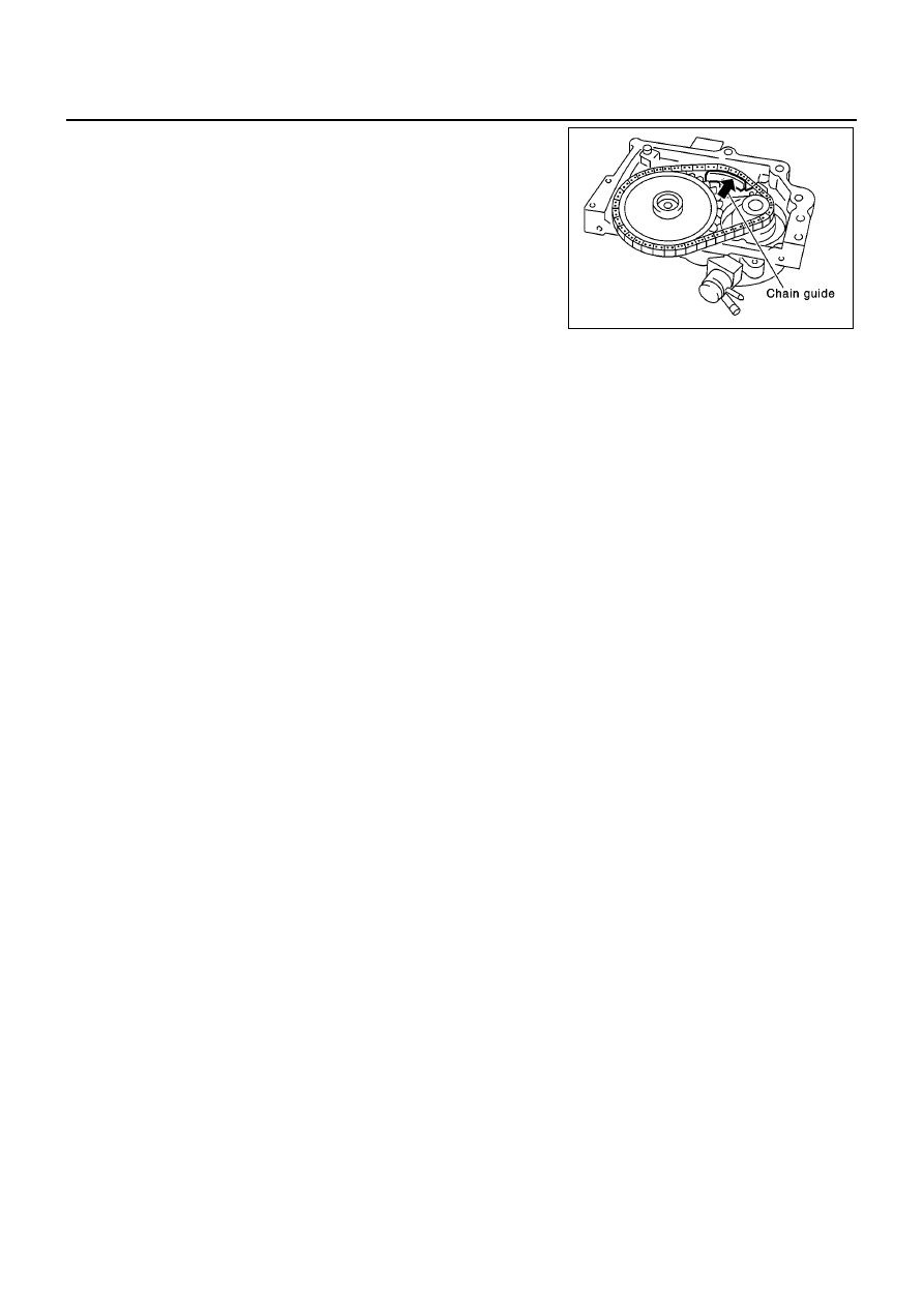
5.
Push on chain guide lightly so that clearance between chain and
chain guide sliding part reaches 0 mm (0 in). Then tighten chain
guide mounting bolts.
SBIA0172E