содержание .. 336 337 338 339 ..
Nissan Primera P12. Manual - part 338
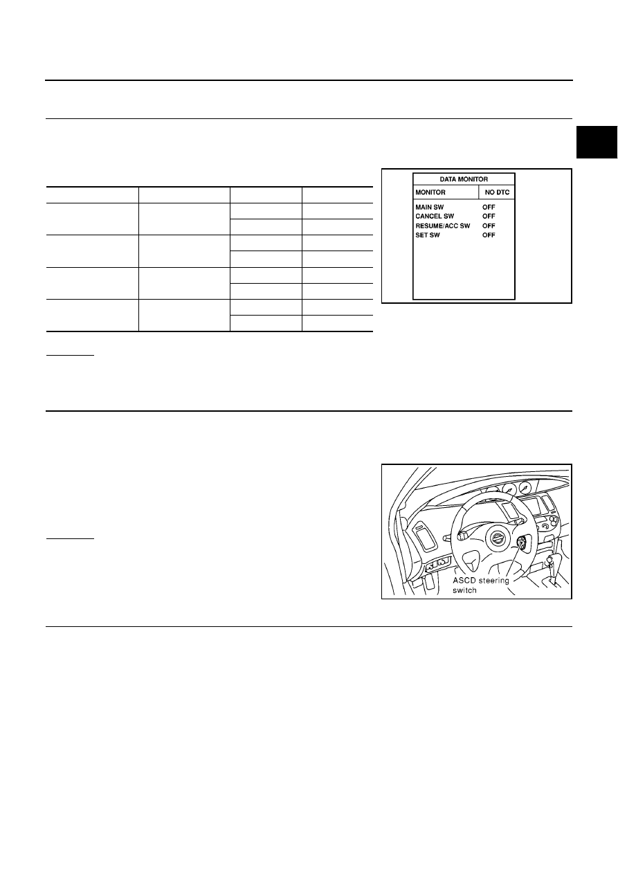
DTC P0580, P0581 ASCD STEERING SWITCH
EC-537
[YD (WITHOUT EURO-OBD)]
C
D
E
F
G
H
I
J
K
L
M
A
EC
Diagnostic Procedure
EBS0158P
1.
CHECK ASCD STEERING SWITCH CIRCUIT
1.
Turn ignition switch ON.
2.
Select “MAIN SW”, “RESUME/ACC SW”, “SET SW” and “CANCEL SW” in “DATA MONITOR” mode with
CONSULT-II.
3.
Check each item indication under the following conditions.
OK or NG
OK
>> GO TO 7.
NG
>> GO TO 2.
2.
CHECK ASCD STEERING SWITCH GROUND CIRCUIT FOR OPEN AND SHORT
1.
Turn ignition switch OFF.
2.
Disconnect ASCD steering harness connector.
3.
Disconnect ECM harness connector.
4.
Check harness continuity between switch terminal 2 and ECM
terminal 103. Refer to Wiring Diagram.
5.
Also check harness for short to ground and short to power.
OK or NG
OK
>> GO TO 4.
NG
>> GO TO 3.
3.
DETECT MALFUNCTIONING PART
Check the following.
●
Harness connectors M77, F109
●
Spiral cable
●
Harness for open and short between ECM and ASCD steering switch
>> Repair open circuit or short to ground short to power in harness or connectors.
Switch
Monitor item
Condition
Indication
ON/OFF
MAIN SW
Pressed
ON
Released
OFF
SET/COAST
SET SW
Pressed
ON
Released
OFF
RESUME/ACCEL
RESUME/ACC SW
Pressed
ON
Released
OFF
CANCEL
CANCEL SW
Pressed
ON
Released
OFF
SEC006D
Continuity should exist.
MBIB0234E