Nissan Primera P12. Manual - part 337


  Главная      Nissan     Nissan Primera P12 - Service Manual


поиск по сайту            


содержание   ..  335  336  337  338   ..


Nissan Primera P12. Manual - part 337


DTC P0563 BATTERY VOLTAGE

EC-533

[YD (WITHOUT EURO-OBD)]

C

D

E

F

G

H

I

J

K

L

M

A

EC

3.

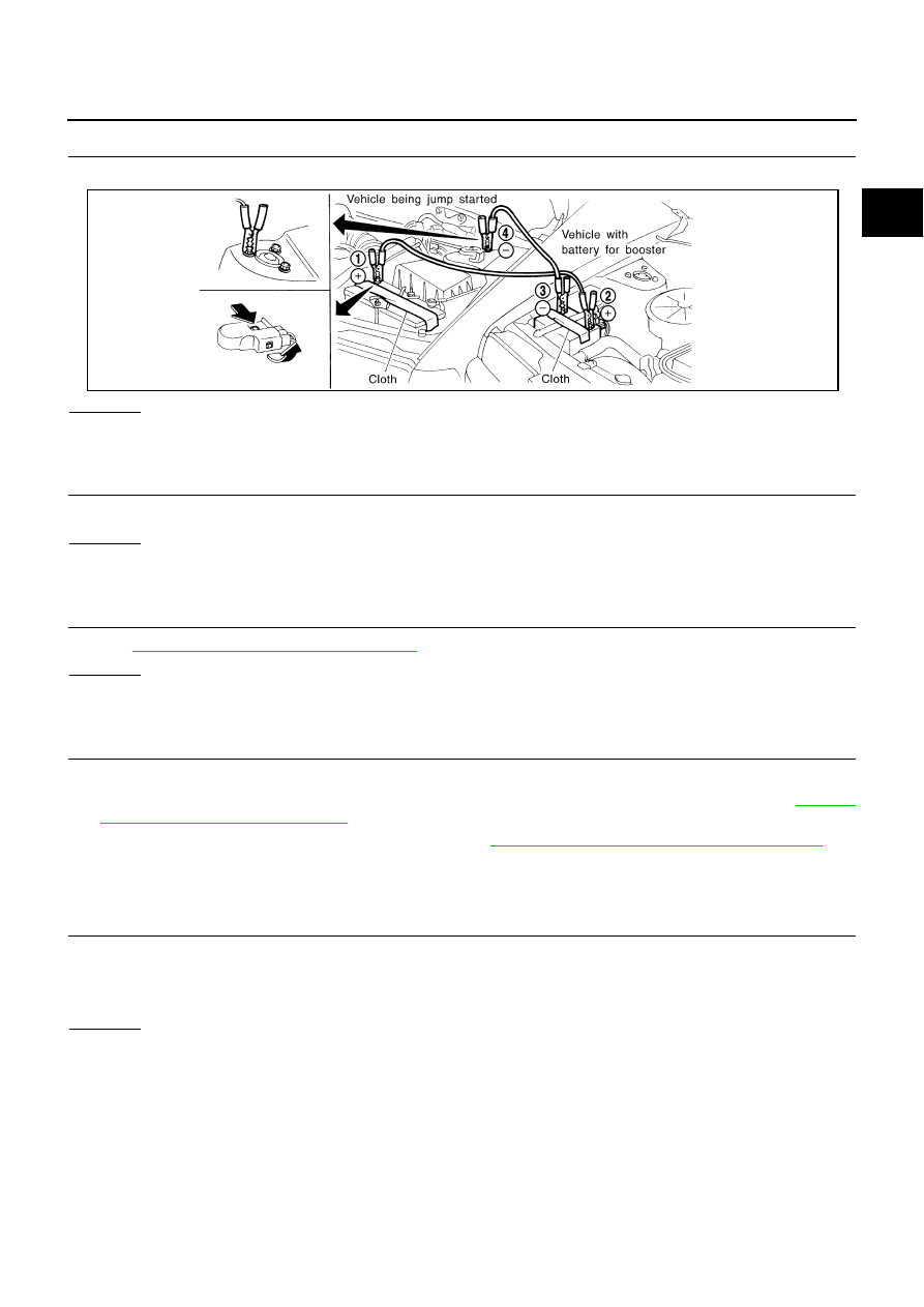
CHECK JUMPER CABLES INSTALLATION

Check that the jumper cables are connected in the correct sequence.

OK or NG

OK

>> GO TO 4.

NG

>> Reconnect jumper cables properly.

4.

CHECK BATTERY FOR BOOSTER

Check that the battery for the booster is a 12V battery.

OK or NG

OK

>> GO TO 5.

NG

>> Change the vehicle for booster.

5.

PERFORM DTC CONFIRMATION PROCEDURE AGAIN

Perform

EC-532, "DTC Confirmation Procedure"

, again.

OK or NG

OK

>> GO TO 7.

NG

>> GO TO 6.

6.

REPLACE ECM

1.

Replace ECM.

2.

Perform initialization of NATS system and registration of all NATS ignition key IDs. Refer to

EC-371,

"NATS (Nissan Anti-theft System)"

.

3.

Perform Fuel Pump Learning Value Clearing. Refer to

EC-368, "Fuel Pump Learning Value Clearing"

.

>> INSPECTION END

7.

CHECK ELECTRICAL PARTS DAMAGE

Check the following for damage.

Wiring harness and harness connectors for burn

Fuses for short

OK or NG

OK

>> INSPECTION END

NG

>> Repair or replace malfunctioning part.

SEF439Z

EC-534

[YD (WITHOUT EURO-OBD)]

DTC P0580, P0581 ASCD STEERING SWITCH

DTC P0580, P0581 ASCD STEERING SWITCH

PFP:25551

Component Description

EBS0158J

ASCD steering switch has variant values of electrical resistance for
each button. ECM reads voltage variation of switch, and determines
which button is operated.
Refer to

EC-653, "AUTOMATIC SPEED CONTROL DEVICE

(ASCD)"

for the ASCD function.

CONSULT-II Reference Value in Data Monitor Mode

EBS0158K

Specification data are reference values.

ECM Terminals and Reference Value

EBS0158L

Specification data are reference values and are measured between each terminal and ground.

CAUTION:

Do not use ECM ground terminals when measuring input/output voltage. Doing so may result in dam-
age to the ECM's transistor. Use a ground other than ECM terminals, such as the ground.

MBIB0234E

MONITOR ITEM

CONDITION

SPECIFICATION

SET SW

Ignition switch: ON

SET/COAST switch: Released

OFF

SET/COAST switch: Pressed

ON

RESUME/ACC SW

Ignition switch: ON

RESUME/ACCEL switch: Released

OFF

RESUME/ACCEL switch: Pressed

ON

CANCEL SW

Ignition switch: ON

CANCEL switch: Released

OFF

CANCEL switch: Pressed

ON

MAIN SW

Ignition switch: ON

ON/OFF switch: Released

OFF

ON/OFF switch: Pressed

ON

TERMI-

NAL

NO.

WIRE

COLOR

ITEM

CONDITION

DATA

(DC Voltage)

102

PU

ASCD steering switch

[Ignition switch ON]

ASCD steering switch is OFF.

Approximately 4.3V

[Ignition switch ON]

ON/OFF switch is ON.

Approximately 0.3V

[Ignition switch ON]

CANCEL switch is ON.

Approximately 1.3V

[Ignition switch ON]

SET/COAST switch is ON.

Approximately 2.3V

[Ignition switch ON]

RESUME/ACCEL switch is ON.

Approximately 3.3V

103

B

ASCD steering switch
ground

[Ignition switch ON]

Approximately 0.3V

DTC P0580, P0581 ASCD STEERING SWITCH

EC-535

[YD (WITHOUT EURO-OBD)]

C

D

E

F

G

H

I

J

K

L

M

A

EC

On Board Diagnosis Logic

EBS0158M

The MI will not light up for this diagnosis.

NOTE:
If DTC P0580 or P0581 is displayed with DTC P0605, first perform the trouble diagnosis for DTC P0605.
Refer to

EC-539, "DTC P0605 ECM"

.

DTC Confirmation Procedure

EBS0158N

NOTE:
If DTC Confirmation Procedure has been previously conducted, always turn ignition switch OFF and wait at
least 10 seconds before conducting the next test.

WITH CONSULT-II

1.

Turn ignition switch ON.

2.

Select “DATA MONITOR” mode with CONSULT-II.

3.

Wait at least 10 seconds.

4.

Press ON/OFF switch for at least 10 seconds, then release it and wait at least 10 seconds.

5.

Press RESUME/ACCEL switch for at least 10 seconds, then release it and wait at least 10 seconds.

6.

Press SET COAST switch for at least 10 seconds, then release it and wait at least 10 seconds.

7.

Press CANCEL switch for at least 10 seconds, then release it and wait at least 10 seconds.

8.

If DTC is detected, go to

EC-537, "Diagnostic Procedure"

.

DTC No.

Trouble Diagnosis

Name

DTC Detecting Condition

Possible Cause

P0580

ASCD steering
switch circuit low

ECM detects that the ASCD steering switch is
stuck ON.

Harness or connectors
(The switch circuit is open or shorted.)

ASCD steering switch

ECM

P0581

ASCD steering
switch circuit high

An excessively high voltage signal from the ASCD
steering switch is sent to ECM.

EC-536

[YD (WITHOUT EURO-OBD)]

DTC P0580, P0581 ASCD STEERING SWITCH

Wiring Diagram

EBS0158O

MBWA0608E


содержание   ..  335  336  337  338   ..