содержание .. 246 247 248 249 ..
Nissan Primera P12. Manual - part 248
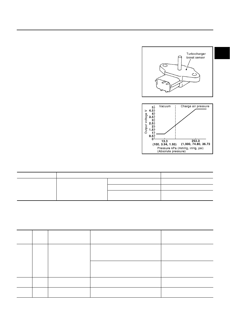
DTC P0237, P0238 TC BOOST SENSOR
EC-177
[YD (WITH EURO-OBD)]
C
D
E
F
G
H
I
J
K
L
M
A
EC
DTC P0237, P0238 TC BOOST SENSOR
PFP:22365
Component Description
EBS013NH
The turbocharger boost sensor detects pressure in the exit side of
the charge air cooler. The sensor output voltage to the ECM
increases as pressure increases.
CONSULT-II Reference Value in Data Monitor Mode
EBS013NI
Specification data are reference values.
ECM Terminals and Reference Value
EBS013NJ
Specification data are reference values, and are measured between each terminal and ground.
CAUTION:
Do not use ECM ground terminals when measuring input/output voltage. Doing so may damage the
ECM's transistor. Use a ground other than ECM terminals, such as the ground.
MBIB0614E
MBIB0899E
MONITOR ITEM
CONDITION
SPECIFICATION
INT/M PRES SE [kPa]
●
Engine: After warming up
●
Air conditioner switch: OFF
●
Shift lever: Neutral position
●
No-load
Idle
Approx. 100 kPa
2,800 rpm
Approx. 126 kPa
4,000 rpm
Approx. 106 kPa
TERMI-
NAL
NO.
WIRE
COLOR
ITEM
CONDITION
DATA
(DC Voltage)
52
Y
Turbocharger boost sensor
[Engine is running]
●
Warm-up condition
●
Idle speed
2.3 - 2.6V
[Engine is running]
●
Warm-up condition
●
Engine speed is 2,000 rpm
2.5 - 2.8V
64
W
Turbocharger boost sensor
power supply
[Ignition switch ON]
Approximately 5.3V
71
B
Turbocharger boost sensor
ground
[Ignition switch ON]
Approximately 0.3V