содержание .. 247 248 249 250 ..
Nissan Primera P12. Manual - part 249
DTC P0237, P0238 TC BOOST SENSOR
EC-181
[YD (WITH EURO-OBD)]
C
D
E
F
G
H
I
J
K
L
M
A
EC
4.
CHECK TURBOCHAGER BOOST SENSOR INPUT SIGNAL CIRCUIT FOR OPEN AND SHORT
1.
Check harness continuity between ECM terminal 52 and turbocharger boost sensor terminal 2. Refer to
Wiring Diagram.
2.
Also check harness for short to ground and short to power.
OK or NG
OK
>> GO TO 5.
NG
>> Repair open circuit or short to ground or short to power in harness connectors.
5.
CHECK TURBOCHARGER BOOST SENSOR
Refer to
EC-181, "Component Inspection"
.
OK or NG
OK
>> GO TO 6.
NG
>> Replace turbocharger boost sensor.
6.
CHECK INTERMITTENT INCIDENT
Refer to
EC-75, "TROUBLE DIAGNOSIS FOR INTERMITTENT INCIDENT"
.
>> INSPECTION END
Component Inspection
EBS013NO
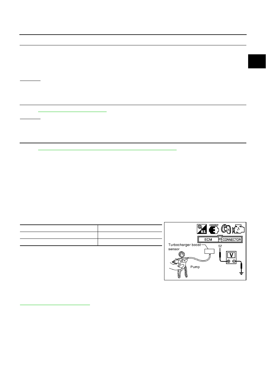
CHECK TURBOCHARGER BOOST SENSOR
1.
Remove turbocharger boost sensor with its harness connected.
2.
Turn ignition switch ON.
3.
Use pump to apply pressure sensor as shown in the figure.
CAUTION:
●
Always calibrate the pressure pump gauge when using it.
●
Inspection should be done at room temperature [10-30
°
C (50-86
°
F)].
4.
Check the output voltage between turbocharger boost sensor terminal 2 and body ground.
Removal and Installation
EBS013NP
TURBOCHARGER BOOST SENSOR
Refer to
Continuity should exist.
Pressure (Relative to atmospheric pressure)
Voltage V
0 kPa (0 mbar, 0 mmHg, 0 inHg)
Approximately 2.3V
+40 kPa (400 mbar, 300mmHg, 11.81 inHg)
Approximately 2.9V
MBIB1093E