Nissan Primera P12. Manual - part 198


  Главная      Nissan     Nissan Primera P12 - Service Manual


поиск по сайту            


содержание   ..  196  197  198  199   ..


Nissan Primera P12. Manual - part 198


WARNING CHIME

DI-121

C

D

E

F

G

H

I

J

L

M

A

B

DI

11.

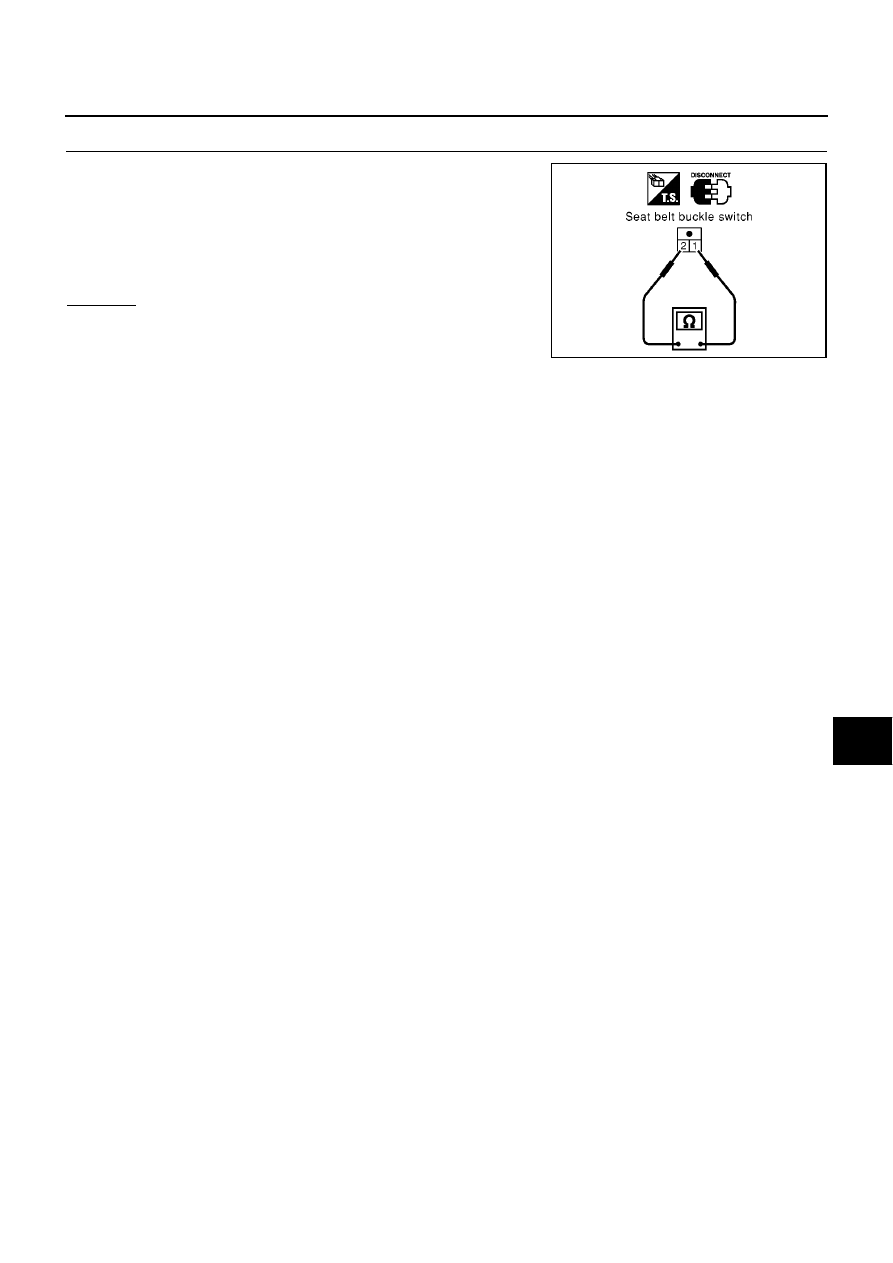
CHECK SEAT BELT BUCKLE SWITCH

Check continuity between seat belt buckle switch (passenger side)
connector B111 terminals 1 and 2.

OK or NG

OK

>> INSPECTION END.

NG

>> Replace seat belt buckle switch (passenger side)

When seat belt
fastened:

Continuity should not exist.

When seat belt
unfastened:

Continuity should exist.

MKIB0022E

DI-122

CLOCK

CLOCK

PFP:25820

Wiring Diagram — CLOCK —

EKS009D2

MKWA1041E

REAR VIEW MONITOR

DI-123

C

D

E

F

G

H

I

J

L

M

A

B

DI

REAR VIEW MONITOR

PFP:28260

System Description

EKS009D3

The rear view monitor is equipped to check the rearward of the vehicle with display when the selector
lever is in R position.

The lines of vehicle sides and the distance from the rear end of the vehicle are provided on display as a
guide. It allows the driver to know the distance between the vehicle and a rearward object, and the width
of the vehicle much easier.

POWER SUPPLY AND GROUND

Power is supplied at all time

through 15 A fuse (No.33, located in fuse and fusible link box)

to rear view camera control unit terminal 7.

When ignition switch is ACC or ON position, power is supplied

through 10 A fuse [No.1, located in fuse block (J/B)]

to rear view camera control unit terminal 6.

When ignition switch is ON or START position, power is supplied

through 10 A fuse [NO.30, located in fuse block (J/B)]

to back

up lamp switch terminal 1 (M/T models) or

to park/neutral position switch terminal 3 (CVT or A/T models).

Ground is supplied
LHD models

to rear view camera control unit terminal 16

through body ground B120, and

to rear view camera terminal 3

through body ground B120 (sedan models), B17, B24 and D94 (wagon models) or B17,B24 and B55
(hatch back models).

RHD models

to rear view camera control unit terminal 16

through body ground B17 and B24 (sedan models), B17, B24 and D94 (wagon models) or B17, B24 and
B55 (hatch back models), and

to rear view camera terminal 3

through body ground B17 and B24 (sedan models), B17, B24 and D94 (wagon models) or B17, B24 and
B55 (hatch back models).

REAR VIEW CAMERA OPERATION

When A/T selector lever is reverse position

through back

up lamp switch terminal 2 (M/T models) or

through park/neutral position switch terminal 8 (CVT or A/T models)

to rear view camera control unit terminal 14, and

to AV and NAVI control unit terminal 32 (with navigation system) or

to display unit terminal 7 (without navigation system).

Then, camera ON signal is sent

through rear view camera control unit terminal 5

to rear view camera terminal 4.

An image taken by rear view camera is sent

through rear view camera terminal 2

to rear view camera control unit terminal 3.

Then an image is sent

through rear view camera control unit terminal 2 and 13

to display terminal 9 and 10 (with navigation system) or

to display unit terminal 23 and 24 (without navigation system).

DI-124

REAR VIEW MONITOR

An image of rear view will be projected on the display.

Rear View Camera Guide Line (With Navigation System)

from AV and NAVI control unit terminal 37

to rear view camera control unit terminal 15.

Rear view guideline will be projected on the display.

Component Location

EKS009D4

MKIB0250E


содержание   ..  196  197  198  199   ..