содержание .. 169 170 171 172 ..
Nissan Primera P12. Manual - part 171
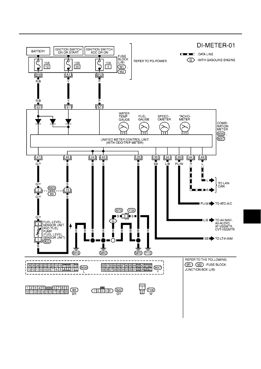
COMBINATION METERS (LHD MODELS)
DI-13
C
D
E
F
G
H
I
J
L
M
A
B
DI
Wiring Diagram — METER —
EKS009A7
MKWA0618E
|
|
|
содержание .. 169 170 171 172 ..
COMBINATION METERS (LHD MODELS) DI-13 C D E F G H I J L M A B DI Wiring Diagram — METER — EKS009A7 MKWA0618E |