Nissan Primera P12. Manual - part 140


  Главная      Nissan     Nissan Primera P12 - Service Manual


поиск по сайту            


содержание   ..  138  139  140  141   ..


Nissan Primera P12. Manual - part 140


TROUBLE DIAGNOSIS

BRC-65

[ESP/TCS/ABS]

C

D

E

G

H

I

J

K

L

M

A

B

BRC

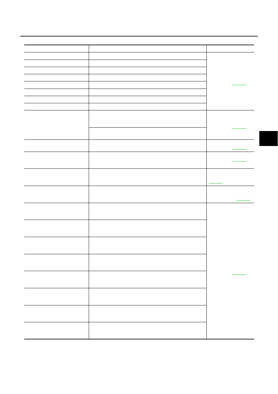
Self-Diagnostic Items to Result Mode

Self-Diagnostic item

Malfunction detecting condition

Check route

FR LH SENSOR – 1

Circuit of front LH wheel sensor is open.

Wheel sensor and cir-
cuit. Refer to

BRC-76

RR RH SENSOR – 1

Circuit of rear RH wheel sensor is open.

FR RH SENSOR – 1

Circuit of front RH wheel sensor is open.

RR LH SENSOR – 1

Circuit of rear LH wheel sensor is open.

FR LH SENSOR – 2

Front LH wheel sensor is shorted or input signal is abnormal.

RR RH SENSOR – 2

Rear RH wheel sensor is shorted or input signal is abnormal.

FR RH SENSOR – 2

Front RH wheel sensor is shorted or input signal is abnormal.

RR LH SENSOR – 2

Rear LH wheel sensor is shorted or input signal is abnormal.

MAIN RELAY

During the actuator relay operation with OFF, when the actuator
relay turns ON. Or when the control line for the relay is shorted to
the ground.

Actuator relay and cir-
cuit. Refer to

BRC-88

During the actuator relay operation with ON, when the actuator
relay turns OFF. Or when the control line for the relay is open.

STOP LAMP SW

Stop lamp switch circuit is open.

Stop lamp switch and cir-
cuit. Refer to

BRC-90

PRESS SEN CIRCUIT

Pressure sensor signal line is open or shorted, or pressure sen-
sor is abnormal.

Pressure sensor and cir-
cuit. Refer to

BRC-79

ST ANGLE SEN CIRCUIT

Neutral position of the steering angle sensor is dislocated, or the
steering angle sensor is abnormal.

Steering angle sensor
and circuit. Refer to

BRC-80

YAW RATE SENOR

Yaw rate sensor is abnormal, or the yaw rate sensor signal line is
open or shorted.

Yaw rate/transverse
acceleration sensor and
circuit. Refer to

BRC-81

FR LH IN ABS SOL

Circuit of the front LH wheel inlet solenoid valve is open or
shorted, or the control line is open or shorted to the power supply
or the ground.

Solenoid valve and cir-
cuit. Refer to

BRC-83

FR LH OUT ABS SOL

Circuit of the front LH wheel outlet solenoid valve is open or
shorted, or the control line is open or shorted to the power supply
or the ground.

RR RH IN ABS SOL

Circuit of the rear RH wheel inlet solenoid valve is open or
shorted, or the control line is open or shorted to the power supply
or the ground.

RR RH OUT ABS SOL

Circuit of the rear RH wheel outlet solenoid valve is open or
shorted, or the control line is open or shorted to the power supply
or the ground.

FR RH IN ABS SOL

Circuit of the front RH wheel inlet solenoid valve is open or
shorted, or the control line is open or shorted to the power supply
or the ground.

FR RH OUT ABS SOL

Circuit of the front RH wheel outlet solenoid valve is open or
shorted, or the control line is open or shorted to the power supply
or the ground.

RR LH IN ABS SOL

Circuit of the rear LH wheel inlet solenoid valve is open or
shorted, or the control line is open or shorted to the power supply
or the ground.

RR LH OUT ABS SOL

Circuit of the rear LH wheel outlet solenoid valve is open or
shorted, or the control line is open or shorted to the power supply
or the ground.

BRC-66

[ESP/TCS/ABS]

TROUBLE DIAGNOSIS

(note) “ACTUATOR RLY” on the CONSULT-II self-diagnosis results indicates the malfunction of the actuator motor relay and circuit.

DATA MONITOR

For details of the data monitor function, refer to the CONSULT-II Instruction Manual.

USV LINE [FL-RR]

ESP switch-over solenoid valve 1 on the primary side is open cir-
cuit or shorted, or the control line is open or shorted to the power
supply or the ground.

ESP switch-over sole-
noid valve and circuit.
Refer to

BRC-83

.

USV LINE [FR-RL]

ESP switch-over solenoid valve 1 on the secondary side is open
circuit or shorted, or the control line is open or shorted to the
power supply or the ground.

HSV LINE [FL-RR]

ESP switch-over solenoid valve 2 on the primary side is open cir-
cuit or shorted, or the control line is open or shorted to the power
supply or the ground.

HSV LINE [FR-RL]

ESP switch-over solenoid valve 2 on the secondary side is open
circuit or shorted, or the control line is open or shorted to the
power supply or the ground.

PUMP MOTOR
ACTUATOR RLY (note)

During the actuator motor operation with ON, when the actuator
motor turns OFF. Or when the control line for actuator motor relay
is open.

Actuator motor, motor
relay, and circuit. Refer
to

BRC-86

During the actuator motor operation with OFF, when the actuator
motor turns ON. Or when the control line for relay is shorted to
ground.

ABS SENSOR
[ABNORMAL SIGNAL]

Wheel sensor input is abnormal.

Wheel sensor and cir-
cuit. Refer to

BRC-76

BATTERY VOLTAGE
[ABNORMAL]

ESP/TCS/ABS control unit battery voltage is too low.

ESP/TCS/ABS control
unit battery voltage cir-
cuit and ground circuit.
Refer to

BRC-90

ST ANGLE SEN SIGNAL

Neutral position correction of steering angle sensor is not fin-
ished.

Neutral position adjust-
ment of steering angle
sensor. Refer to

BRC-37

ST ANG SEN COM CIR

CAN communication system or steering angle sensor is abnor-
mal.

Steering angle sensor
and CAN communication
circuit. Refer to

BRC-94

SIDE G-SEN CIRCUIT

Side G sensor is abnormal, or the signal line of side G sensor is
open or shorted.

Yaw rate /Side G sensor
and circuit. Refer to

BRC-81

EMERGENCY BRAKE

ESP/TCS/ABS control unit malfunction (pressure increase is too
much or too little.)

ESP/TCS/ABS control
unit. Refer to

BRC-92

CONTROLLER FAILURE

ESP/TCS/ABS internal malfunction of control unit

ESP/TCS/ABS control
unit. Refer to

BRC-78

CAN COMM CIRCUIT

CAN communication line is open or shorted.

ESP/TCS/ABS control unit internal malfunction.

Battery voltage for EMC is interrupted instantaneously for
Approx. 0.5 seconds or more.

Communication circuit
between ESP/TCS/ABS
control unit and units.
Refer to

BRC-94

BR FLUID LEVEL LOW

Brake fluid level drops or communication line between the ESP/
TCS/ABS control unit and the brake fluid level warning switch is
open or shorted.

Communication circuit
between the ESP/TCS/
ABS control unit and the
brake fluid level warning
switch.
Reservoir tank fluid.
Refer to

BRC-93

ENGINE SIGNAL 1 - 4, 6

Major engine components are abnormal

Engine system. Refer to

BRC-78

Self-Diagnostic item

Malfunction detecting condition

Check route

TROUBLE DIAGNOSIS

BRC-67

[ESP/TCS/ABS]

C

D

E

G

H

I

J

K

L

M

A

B

BRC

Procedure

1.

Turn the ignition switch OFF.

2.

Connect the CONSULT-II connector to the vehicle-side data link connector.

3.

Turn the ignition switch ON.

4.

Touch “START (NISSAN BASED VHCL)” on the display.

5.

Touch “ABS” on the display.

CAUTION:

Just after the engine is started, or the ignition switch is
turned ON, “ABS” may not be displayed on the system
selection screen even if “START (NISSAN BASED VHCL)” is
touched. In this case, start the self-diagnosis again from
step 2.

6.

Touch “DATA MONITOR”.

7.

The data monitor item selection screen is displayed, and touch
one of “ECU INPUT SIGNALS” “MAIN SIGNALS”, “CAN DIAG
SUPPORT MNTR” or “SELECTION FROM MENU”. Refer to

BRC-67, "Data Monitor Items to be Displayed"

.

8.

Touch “START”.

9.

Screen of data monitor is displayed.

Data Monitor Items to be Displayed

MBIB0233E

PBR385C

SFIA0365E

Data Monitor Item (Unit)

Data Monitor item selection

Remarks

ECU INPUT

SIGNALS

MAIN

SIGNALS

SELECTION

FROM
MENU

CAN DIAG
SUPPORT

MNTR

GEAR

×

×

×

“1” is displayed.

SLCT LVR POSI

×

×

×

“##” is displayed.

FR RH SENSOR

(km/h, MPH)

×

×

×

Wheel speed calculated by
front RH wheel sensor signal
is displayed.

FR LH SENSOR

(km/h, MPH)

×

×

×

Wheel speed calculated by
front LH wheel sensor signal
is displayed.

RR RH SENSOR

(km/h, MPH)

×

×

×

Wheel speed calculated by
rear RH wheel sensor signal
is displayed.

BRC-68

[ESP/TCS/ABS]

TROUBLE DIAGNOSIS

RR LH SENSOR
(km/h, MPH)

×

×

×

Wheel speed calculated by
rear LH wheel sensor signal is
displayed.

ACCEL POS SIG
(%)

×

×

×

Throttle valve open/close sta-
tus judged by the CAN com-
munication signal is
displayed.

ENGINE RPM
(rpm)

×

×

×

Engine speed judged by the
CAN communication signal is
displayed.

CAN COM START
(ON/OFF)

×

×

Communication status of CAN
communication is displayed.

STR ANGLE SIG
(deg)

×

×

×

Steering angle detected by
the steering angle sensor is
displayed.

YAW RATE SEN
(d/s)

×

×

×

Yaw rate detected by the yaw
rate sensor is displayed.

SIDE G-SENSOR

(m/s

2

)

×

×

×

Transverse acceleration
detected by the side G sensor
is displayed.

PRESS SENSOR
(bar )

×

×

×

Brake fluid pressure detected
by the pressure sensor is dis-
played.

BATTERY VOLT
(V )

×

×

×

Voltage supplied to ESP/TCS/
ABS control unit is displayed.

MOTOR RELAY
(ON/OFF )

×

×

Motor relay signal (ON/OFF)
status is displayed.

ACTUATOR RLY
(ON/OFF )

×

×

Actuator relay signal (ON/
OFF) status is displayed.

STOP LAMP SW
(ON/OFF)

×

×

×

Stop lamp switch (ON/OFF)
status is displayed.

PARK BRAKE SW
(ON/OFF)

×

×

×

Parking brake switch (ON/
OFF) status is displayed.

OFF SW

(ON/OFF)

×

×

×

ESP OFF switch (ON/OFF)
status is displayed.

ABS WARN LAMP
(ON/OFF)

×

×

ABS warning lamp (ON/OFF)
status is displayed.

OFF LAMP
(ON/OFF)

×

×

ESP OFF indicator lamp (ON/
OFF) status is displayed.

SLIP LAMP

(ON/OFF)

×

×

SLIP indicator lamp (ON/
OFF) status is displayed.

FR LH IN SOL

(ON/OFF)

×

×

Front LH wheel inlet solenoid
valve (ON/OFF) status is dis-
played.

FR LH OUT SOL

(ON/OFF)

×

×

Front LH wheel outlet sole-
noid valve (ON/OFF) status is
displayed.

RR RH IN SOL

(ON/OFF)

×

×

Rear RH wheel inlet solenoid
valve (ON/OFF) status is dis-
played.

Data Monitor Item (Unit)

Data Monitor item selection

Remarks

ECU INPUT

SIGNALS

MAIN

SIGNALS

SELECTION

FROM
MENU

CAN DIAG
SUPPORT

MNTR


содержание   ..  138  139  140  141   ..