содержание .. 136 137 138 139 ..
Nissan Primera P12. Manual - part 138
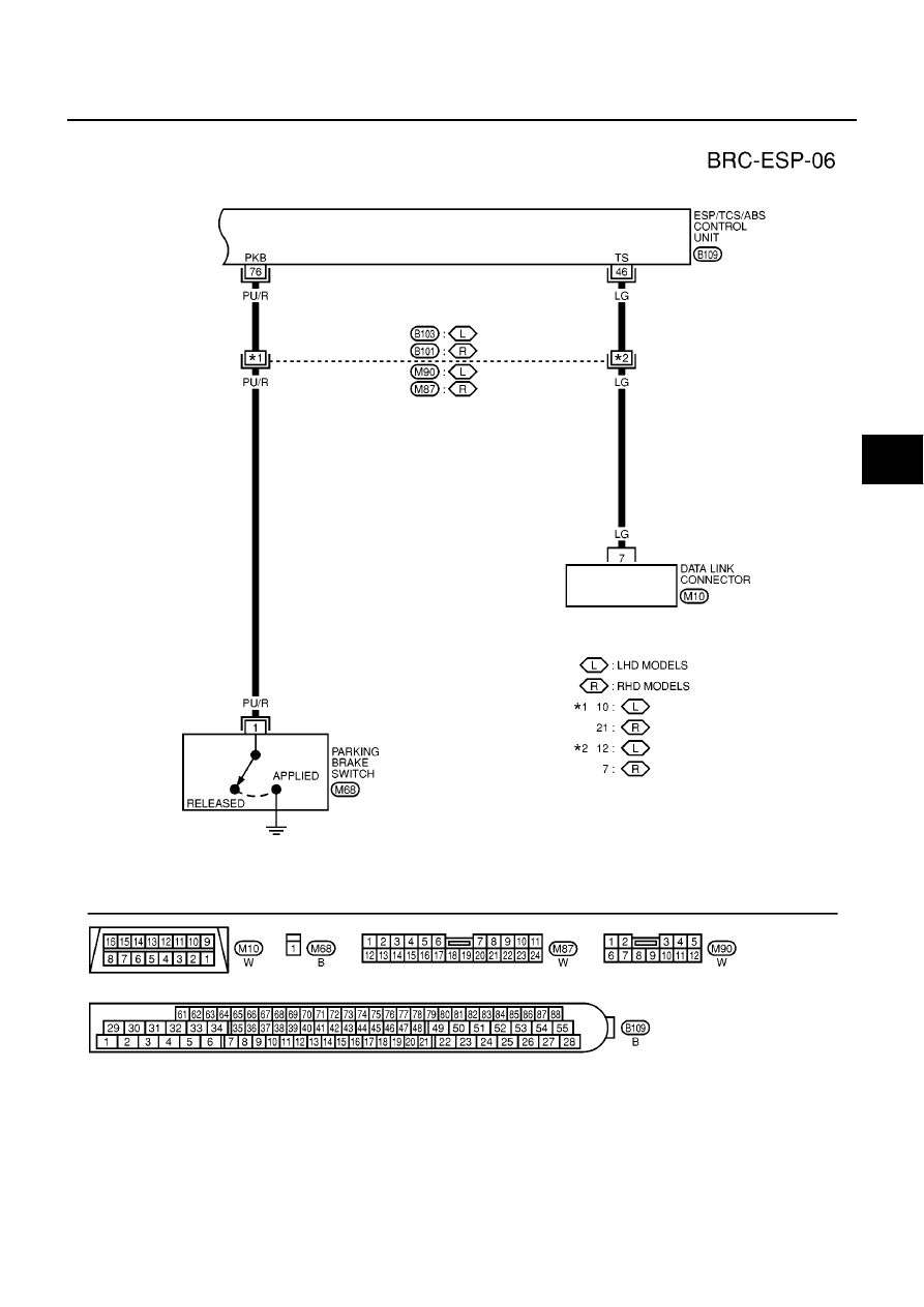
TROUBLE DIAGNOSIS
BRC-57
[ESP/TCS/ABS]
C
D
E
G
H
I
J
K
L
M
A
B
BRC
MFWA0007E
|
|
|
содержание .. 136 137 138 139 ..
TROUBLE DIAGNOSIS BRC-57 [ESP/TCS/ABS] C D E G H I J K L M A B BRC MFWA0007E |