Nissan Primera P12. Manual - part 117


  Главная      Nissan     Nissan Primera P12 - Service Manual


поиск по сайту            


содержание   ..  115  116  117  118   ..


Nissan Primera P12. Manual - part 117


BRAKE PEDAL

BR-7

C

D

E

G

H

I

J

K

L

M

A

B

BR

1.

Loosen stop lamp switch by rotating it counter-clockwise by 45

°

.

2.

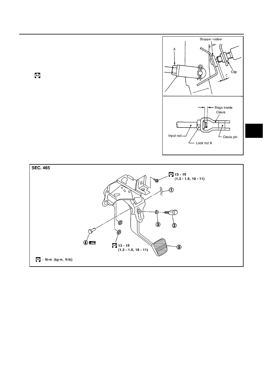
Loosen input rod lock nut (A), then rotate input rod, set pedal to
the specified height, and tighten lock nut (A).

CAUTION:

Confirm threaded end of input rod remains inside the cle-
vis.

3.

Pull pedal by hand and hold it. Press stop lamp switch until its
threaded end contacts the stopper rubber.

4.

While holding it against the stopper rubber, turn the switch clock-
wise by 45

°

and secure it.

CAUTION:

Be sure stopper rubber to stop lamp switch screw threaded
end gap (C) is within specifications.

5.

Check pedal free play.

CAUTION:

Be sure stop lamps go off when pedal is released.

6.

Start the engine and check brake pedal depressed height.

Components

EFS002UR

Removal and Installation

EFS002US

REMOVAL

Be careful not to deform brake tube.
1.

Remove the instrument of the driver-side lower panel.

2.

Remove stop lamp switch from brake pedal assembly.

3.

Remove snap pin and clevis pin from brake booster clevis.

4.

Remove brake pedal assembly mounting nuts. Pull brake booster toward the engine compartment. Be
careful not to deform the brake tube.

5.

Remove brake booster clevis from input rod.

6.

Remove steering column assembly from steering member.

: 15.7 - 21.6 N·m (1.6 - 2.2 kg-m, 12 - 15 ft-lb)

SFIA0160E

SFIA0474E

1.

Snap pin

2.

Stop lamp switch

3.

Clip

4.

Clevis pin

5.

Brake pedal assembly

BR-8

BRAKE PEDAL

INSPECTION AFTER REMOVAL

Check brake pedal for the following.

Bent brake pedal

Deformed clevis pin

Cracks in welded area

Cracked or deformed clevis pin stopper

INSTALLATION

Install in reverse order of removal. Be careful of the following:

Adjust brake pedal assembly after installing it.

SBR997

BRAKE FLUID

BR-9

C

D

E

G

H

I

J

K

L

M

A

B

BR

BRAKE FLUID

PFP:KN100

Checking Brake Fluid Level

EFS002UT

Confirm reservoir tank fluid level is within specifications
(between MAX and MIN lines).

Visually check around reservoir tank for fluid leaks.

If fluid level is excessively low, check brake system for leaks.

If warning lamp remains illuminated after parking lever is
released, check brake system for fluid leakage.

Checking Brake Line

EFS002UU

CAUTION:

If leakage occurs around joints, retighten or, if necessary, replace damaged parts.

1.

Check brake line (tube and hoses) for cracks, deterioration or
other damage. Replace and damaged parts.

2.

Check for oil leakage by fully depressing brake pedal while
engine is running.

Changing Brake Fluid

EFS002UV

CAUTION:

Refill with new brake fluid “DOT 3 or DOT 4”.

Always keep fluid level higher than minimum line on reservoir tank.

Never reuse drained brake fluid.

Be careful not to splash brake fluid on spill or splash on painted areas; it may cause paint damage.
If brake fluid is splashed on painted areas, wash it away water immediately.

1.

Connect a vinyl tube to the air bleeder.

2.

Drain brake fluid gradually from the air bleeder of each wheel
while depressing the brake pedal.

3.

Turn OFF ignition switch. Remove ABS actuator connector.

SFIA0066J

SBR389C

BRA0007D

BR-10

BRAKE FLUID

4.

Be sure there is no foreign material in reservoir tank. Refill with
new brake fluid.

5.

Connect a vinyl tube to the air bleeder.

6.

Rest foot on brake pedal. Loosen air bleeder. Slowly depress
pedal until it stops. Tighten air bleeder. Release brake pedal.
Repeat this process a few times, then pause to add new brake
fluid to master cylinder. Continue until new brake fluid flows out.
For bleeding procedure. Refer to

BR-10, "Bleeding Brake Sys-

tem"

.

Bleeding Brake System

EFS002UW

CAUTION:

Carefully monitor brake fluid level at master cylinder during bleeding operation.

Fill reservoir with new brake fluid “DOT 3” or “DOT 4”. Make sure it is full at all times while bleed-
ing air out of system.

Place a container under master cylinder to avoid spillage of brake fluid.

While bleeding, pay attention to master cylinder fluid level.

For models with ABS, turn ignition switch OFF and disconnect ABS actuator connectors or bat-
tery ground cable.

Bleed air in the following order.
Right rear brake, Left front brake, Left rear brake, Right front brake

1.

Turn OFF ignition switch. Remove ABS actuator connector.

2.

Connect a vinyl tube to the air bleeder.

3.

Fully depress the brake pedal 4 to 5 times.

4.

With brake pedal depressed, loosen air bleeder and bleed air.

5.

Close air bleeder.

6.

Slowly release brake pedal.

7.

Tighten air bleeder to the specified torque.

8.

Repeat steps 2 - 7. Occasionally refill master cylinder reservoir tank. Be sure to keep it at least half-full.

BRA0006D

Front caliper

: 7 - 13 N·m (0.72 - 1.3 kg-m, 62 - 115 in-lb)

Rear caliper

: 12 - 16 N·m (1.3 - 1.6 kg-m, 9 - 11 ft-lb)


содержание   ..  115  116  117  118   ..