содержание .. 116 117 118 119 ..
Nissan Primera P12. Manual - part 118
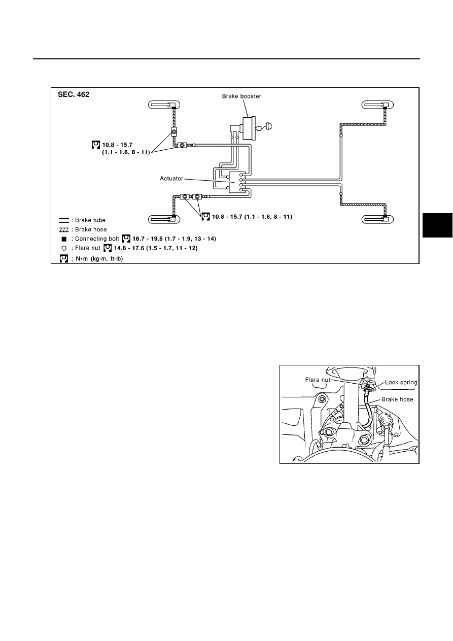
BRAKE PIPING AND HOSE
BR-11
C
D
E
G
H
I
J
K
L
M
A
B
BR
BRAKE PIPING AND HOSE
PFP:46210
Hydraulic Piping
EFS002UX
Removal and Installation of Front Brake Piping and Brake Hose
EFS002UY
REMOVAL
CAUTION:
●
Do not allow brake fluid to spill or splash on painted surfaces. Brake fluid can seriously damage
paint. If it gets on a painted surface, wipe it off immediately and wash with water.
●
Do not bend or twist the brake hose sharply, or strongly pull it.
●
Cover brake fluid line connections to prevent dust and other foreign material from entering.
1.
Connect a vinyl tube to the air bleeder.
2.
Drain brake fluid gradually from the air bleeder of each wheel while depressing the brake pedal.
3.
Using a flare nut wrench, remove brake tube flare nuts and dis-
connect brake tube from the brake hose.
4.
Remove union bolts and disconnect caliper assembly from the
brake hose.
5.
First remove lock spring from brake tube and strut mounting
positions. Then remove brake hose.
INSTALLATION
CAUTION:
●
Refill with new brake fluid “DOT 3” or “DOT4”.
●
Never reuse drained brake fluid.
1.
Connect brake hose to caliper assembly and tighten union bolts to the specified torque.
CAUTION:
●
Securely connect brake hose to the protrusions on the cylinder body.
●
Do not reuse the copper washer for union bolts.
2.
Connect brake hose to the strut and fix with lock spring.
3.
Connect brake hose to brake tube. Temporarily tighten flare nuts by hand as far as they will go. Secure
them with the lock spring.
4.
Using a flare nut torque wrench, tighten to the specified torque.
SFIA0465E
SFIA0475E