Nissan Primera P12. Manual - part 39


  Главная      Nissan     Nissan Primera P12 - Service Manual


поиск по сайту            


содержание   ..  37  38  39  40   ..


Nissan Primera P12. Manual - part 39


REFRIGERANT LINES

ATC-149

C

D

E

F

G

H

I

K

L

M

A

B

ATC

Service valves
Check all around the service valves. Ensure service valve caps are secured on the service valves (to pre-
vent leaks).

NOTE:
After removing A/C manifold gauge set from service valves, wipe any residue from valves to prevent any
false readings by leak detector.

Cooling unit (Evaporator)
With engine OFF, turn blower fan on “High” for at least 15 seconds to dissipate any refrigerant trace in the
cooling unit. Wait a minimum of 10 minutes accumulation time (refer to the manufacturer

s recommended

procedure for actual wait time) before inserting the leak detector probe into the drain hose.
Keep the probe inserted for at least 10 seconds. Use caution not to contaminate the probe tip with water
or dirt that may be in the drain hose.

5.

If a leak detector detects a leak, verify at least once by blowing compressed air into area of suspected
leak, then repeat check as outlined above.

6.

Do not stop when one leak is found. Continue to check for additional leaks at all system components.
If no leaks are found, perform steps 7 - 10.

7.

Start engine.

8.

Set the heater A/C control as follows;

a.

A/C switch: ON

b.

Face mode

c.

Intake position: Recirculation

d.

Max cold temperature

e.

Fan speed: High

9.

Run engine at 1,500 rpm for at least 2 minutes.

10. Turn engine OFF and perform leak check again following steps 4 through 6 above.

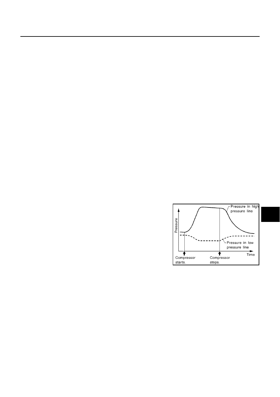
Refrigerant leaks should be checked immediately after stopping the
engine. Begin with the leak detector at the compressor. The pres-
sure on the high-pressure side will gradually drop after refrigerant
circulation stops and pressure on the low-pressure side will gradually
rise, as shown in the graph. Some leaks are more easily detected
when pressure is high.

11. Before connecting ACR4 to vehicle, check ACR4 gauges. No refrigerant pressure should be displayed. If

pressure is displayed, recover refrigerant from equipment lines and then check refrigerant purity.

12. Discharge A/C system using approved refrigerant recovery equipment. Repair the leaking fitting or com-

ponent as necessary.

13. Evacuate and recharge A/C system and perform the leak test to confirm no refrigerant leaks.

14. Conduct A/C performance test to ensure system works properly.

SHA839E

ATC-150

SERVICE DATA AND SPECIFICATIONS (SDS)

SERVICE DATA AND SPECIFICATIONS (SDS)

PFP:00030

Compressor

EJS002ZC

Lubricant

EJS002ZD

Refrigerant

EJS002ZE

Engine Idling Speed

EJS002ZF

Refer to

EC-350, "SERVICE DATA AND SPECIFICATIONS (SDS)"

for YD engine.

Belt Tension

EJS002ZG

Refer to

EM-115, "SERVICE DATA AND SPECIFICATIONS (SDS)"

for YD engine,

EM-142, "DRIVE BELTS"

for F9Q engine.

Model

With YD engine

With F9Q engine

Calsonic Kansei make CSV-613

Delphi make 6CVC

Type

V-6 variable displacement

Swash plate

Displacement

cm

3

(cu in)/rev

Max.

125 (7.63)

135 (8.24)

Min.

6.0 (0.37)

Cylinder bore

×

stroke

mm (in)

32 (1.26)

×

[1.2 - 25.9 (0.05 - 1.02)]

Direction of rotation

Clockwise (viewed from drive end)

Drive belt

Type A

Poly V

Model

YD engine models

F9Q engine models

Name

Nissan A/C System Oil Type S

Part number

KLH00-PAGS0

Capacity

m

(lmp fl oz)

Total in system

180 (6.3)

Compressor (service part) charging
amount

180 (6.3)

Type

HFC-134a (R-134a)

Capacity
kg (lb)

0.50 (1.10)

AV-1

AUDIO, VISUAL, NAVIGATION & TELEPHON

E

SYS

TEM

K ELECTRICAL

CONTENTS

C

D

E

F

G

H

I

J

L

M

SECTION

A

B

AV

AUDIO, VISUAL, NAVIGATION & TELEPHONE SYSTEM

PRECAUTIONS .......................................................... 3

Precautions for Supplemental Restraint System
(SRS) “AIR BAG” and “SEAT BELT PRE-TEN-
SIONER” .................................................................. 3
Wiring Diagrams and Trouble Diagnosis .................. 3

AUDIO ......................................................................... 4

System Description .................................................. 4

AUDIO SYSTEM ................................................... 4
AV COMMUNICATION LINE ................................. 5
NAVIGATION SYSTEM OF GUIDANCE VOICE
OPERATION ......................................................... 5
NATS AUDIO LINK ............................................... 5
SPEED DEPENDENT VOLUME CONTROL ........ 6
PERSONAL AUDIO SETTINGS ........................... 6

Component Parts Location ....................................... 6
Schematic ................................................................ 7

WITHOUT NAVIGATION SYSTEM ....................... 7
WITH NAVIGATION SYSTEM ............................... 8

Wiring Diagram—AUDIO— ...................................... 9

WTIHOUT NAVIGATION SYSTEM FOR LHD
MODELS ............................................................... 9
WITHOUT NAVIGATION SYSTEM FOR RHD
MODELS ............................................................. 13
WITH NAVIGATION SYSTEM FOR LHD MOD-
ELS ..................................................................... 17
WITH NAVIGATION SYSTEM FOR RHD MOD-
ELS ..................................................................... 22

Terminals and Reference Value for Audio Unit ....... 26
Terminals and Reference Value for Sub-woofer ..... 30
Terminals and Reference Value for CD Auto
Changer ................................................................. 31
Self-Diagnosis Function ......................................... 32

DESCRIPTION .................................................... 32
DIAGNOSIS ITEM ............................................... 32

Self-Diagnosis Mode .............................................. 32

OPERATION PROCEDURE ............................... 32

Trouble Diagnosis .................................................. 32

PROBLEM WITH RADIO, TAPE, AND CD ......... 32
FOR RADIO ONLY .............................................. 32
FOR CD ONLY .................................................... 33

Noise Inspection ..................................................... 33

TYPE OF NOISE AND POSSIBLE CAUSE ........ 33

Power Supply Circuit Inspection ............................. 34
Audio System Does Not Turn On ........................... 34
Removal and Installation of Audio Unit ................... 35
Removal and Installation of Door Speaker ............. 35
Removal and Installation of Front Pillar Tweeter .... 35

AUDIO ANTENNA .................................................... 36

Location of Antenna ................................................ 36
Removal and Installation of Roof Antenna ............. 37

TELEPHONE (PRE WIRE) ....................................... 38

Wiring Diagram — PHONE — ................................ 38

NAVIGATION SYSTEM ............................................. 39

System Description ................................................. 39

TRAVEL DISTANCE ............................................ 39
TRAVEL DIRECTION .......................................... 39
MAP-MATCHING ................................................. 39
GPS (GLOBAL POSITIONING SYSTEM) ........... 40
COMPONENT DESCRIPTION ............................ 41
BIRDVIEW® ........................................................ 41
MAP DISPLAY ..................................................... 42
FUNCTION OF MULTIFUNCTION SWITCH ....... 43
“VIEW” MODE ..................................................... 46
“HEADING” MODE .............................................. 46
“NEARBY DISPLAY ICONS” MODE ................... 47
“SAVE CURRENT LOCATION” MODE ............... 47
“EDIT ADDRESS BOOK” MODE ........................ 47
“CLEAR MEMORY” MODE ................................. 47
“AUTO RE-ROUTE” MODE ................................. 48
“QUICK STOP CUSTOMER SETTINGS” MODE... 48
“SET AVERAGE SPEED FOR ESTIMATED
JOURNEY TIME” MODE ..................................... 48
“GPS INFORMATION” MODE ............................. 48
“TRACKING” MODE ............................................ 49
“ADJUST CURRENT LOCATION” MODE ........... 49
GUIDE VOLUME SETTING ................................ 49
NATS NAVI LINK ................................................. 50

Precautions for AV and NAVI Control Unit Replace-
ment ........................................................................ 50
Component Parts Location ..................................... 51

AV-2

Location of Antenna ................................................ 52
Schematic ............................................................... 53
Wiring Diagram —NAVI— ....................................... 54

EXCEPT FOR YD22DDTI AND F9Q ENGINE
MODELS ............................................................. 55
FOR YD22DDTI AND F9Q ENGINE MODELS ... 56

Schematic for AV Communication Line .................. 61
Wiring Diagram — COMM — ................................. 62
Terminals and Reference Value for AV and NAVI
Control Unit ............................................................. 65
Terminals and Reference Value for Display ............ 68
Terminals and Reference Value for Multifunction
Switch ..................................................................... 70
Self-Diagnosis Function .......................................... 71

DESCRIPTION .................................................... 71
SELF-DIAGNOSIS ITEM ..................................... 71

Self-Diagnosis Mode .............................................. 71

OPERATION PROCEDURE ................................ 71
DIAGNOSIS CHART ........................................... 73
DIAGNOSIS NUMBER CHART ........................... 73

CONFIRMATION/ADJUSTMENT Mode ................. 74

OPERATION PROCEDURE ................................ 74
DISPLAY .............................................................. 75
VEHICLE SIGNALS ............................................. 75
NAVIGATION ....................................................... 76
HISTORY OF ERRORS ...................................... 77
DIAGNOSIS BY HISTORY OF ERRORS ............ 77
AUTO CLIMATE CONTROL ................................ 79
SERVICE ............................................................. 79

Power Supply and Ground Circuit Check ............... 80
Check Display, Multifunction Switch Power, and
Ground Circuit ........................................................ 81
Vehicle Speed Signal Check .................................. 82
Illumination Control Signal Check ........................... 83
Ignition Signal Check .............................................. 84
Reverse Signal Check ............................................ 84
RGB Screen Is Not Shown ..................................... 85
No Screens Appear ................................................ 86
Color of RGB Image Is Not Proper ......................... 86
RGB Screen Is Rolling ............................................ 89
Guide Sound Is Not Heard ..................................... 89
Multifunction Switch Controls Are Ineffective (Rear
Defogger Control Excluded) ................................... 90
Air Conditioning Controls (Only) Are Ineffective
(Rear Defogger Control Excluded) ......................... 93
Rear Defogger Does Not Operate .......................... 94
Rear Defogger Indicator Lamp Does Not Illuminate... 95
No Fuel Information Is Displayed/No Warning Mes-
sage Is Displayed ................................................... 95
Previous Conditions Are Not Stored ....................... 97
The Position of The Current-Location Mark Is Not
Correct .................................................................... 97

Radio Wave From The GPS Satellite Is Not
Received .................................................................97
Display Does Not Change When Screen Adjust-
ment Is Performed ..................................................97
Day/Night Display Switching Is Not Done. Night Illu-
mination for AV and NAVI Control Unit Does Not Illu-
minate .....................................................................98
On Multifunction Switch, a Specific Switch Does Not
Operate in All Conditions ........................................98
Driving Information Is Inaccurate. Maintenance
Information Is Inaccurate ........................................98
System Does Not Start ............................................98
The Current Position Mark Is in the Wrong Place ...98
The Current-Location Mark Will Not Move Forward/
Backward ................................................................99
The Position of the Current-Location Mark Is Not
Correct ....................................................................99
Driving Test ...........................................................100
Example of Symptoms Judged Not Abnormal ......101

BASIC OPERATION ..........................................101
VEHICLE MARK ................................................101
DESTINATION, PASSING POINTS, AND MENU
ITEMS CANNOT BE SELECTED/SET ..............101
VOICE GUIDE ...................................................102
ROUTE SEARCHING ........................................102
EXAMPLES OF CURRENT-LOCATION MARK
DISPLACEMENT ...............................................103
THE CURRENT POSITION MARK SHOWS A
POSITION WHICH IS COMPLETELY WRONG.106
THE CURRENT POSITION MARK JUMPS ......106
THE CURRENT LOCATION MARK IS IN A
RIVER OR THE SEA .........................................107
WHEN DRIVING ON THE SAME ROAD, SOME-
TIMES THE CURRENT-LOCATION MARK IS IN
THERIGHTPLACEAND SOMETIMESITISTHE
WRONG PLACE ................................................107
LOCATION CORRECTION BY MAP MATCHING
IS SLOW ............................................................107
ALTHOUGH THE GPS RECEIVING DISPLAY IS
GREEN, THE VEHICLE MARK DOES NOT
RETURN TO THE CORRECT LOCATION ........107
THE NAME OF THE CURRENT PLACE IS NOT
DISPLAYED .......................................................107
CONTENTS OF THE DISPLAY DIFFER FOR
THE BIRDVIEW® AND THE (FLAT) MAP
SCREEN ............................................................107

Program Loading ..................................................108
Removal and Installation of AV&NAVI Control Unit.108
Removal and Installation of GPS Antenna ............109
Removal and Installation of Multifunction Switch ..109
Removal and Installation of Display Assembly .....109


содержание   ..  37  38  39  40   ..