Nissan Primera P12. Manual - part 24


  Главная      Nissan     Nissan Primera P12 - Service Manual


поиск по сайту            


содержание   ..  22  23  24  25   ..


Nissan Primera P12. Manual - part 24


TROUBLE DIAGNOSIS

ATC-89

C

D

E

F

G

H

I

K

L

M

A

B

ATC

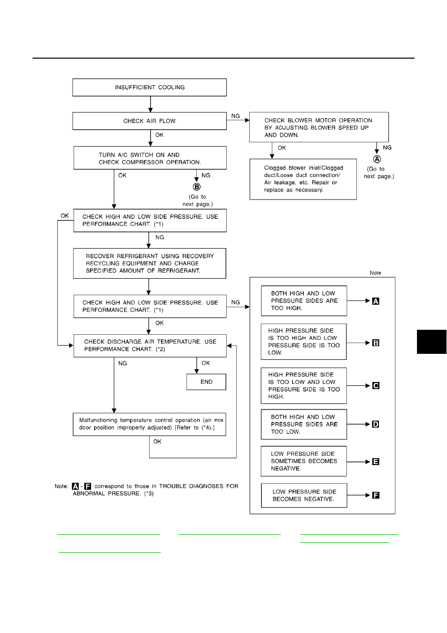
PERFORMANCE TEST DIAGNOSES

*1

ATC-91, "PERFORMANCE CHART"

*2

ATC-91, "PERFORMANCE CHART"

*3

ATC-92, "TROUBLE DIAGNOSES
FOR ABNORMAL PRESSURE"

*4

ATC-67, "Air Mix Door Motor Circuit"

SHA344F

TROUBLE DIAGNOSIS

ATC-91

C

D

E

F

G

H

I

K

L

M

A

B

ATC

PERFORMANCE CHART
Test Condition

Testing must be performed as follows:

Test Reading (YD Engine)

Recirculating-to-discharge Air Temperature Table

Ambient Air Temperature-to-operating Pressure Table

Vehicle location

Indoors or in the shade (in a well-ventilated place)

Doors

Closed

Door windows

Open

Hood

Open

TEMP.

Max. COLD

Mode switch

(Ventilation) set

Intake switch

(Recirculation) set

(blower) speed

Max. speed set

Engine speed

Idle speed

Operate the air conditioning system for 10 minutes before taking measurements.

Inside air (Recirculating air) at blower assembly inlet

Discharge air temperature at center ventilator

°

C (

°

F)

Relative humidity

%

Air temperature

°

C (

°

F)

50 - 60

20 (68)

6.5 - 9.0 (44 - 48)

25 (77)

12 - 14 (54 - 57)

30 (86)

15.5 - 18.8 (60 - 66)

35 (95)

20.4 - 24.0 (69 - 75)

60 - 70

20 (68)

9.0 - 11.0 (48 - 52)

25(77)

14.0 - 16.5 (57 - 62)

30 (86)

18.8 - 21.5 (66 - 71)

35 (95)

24 - 27 (75 - 81)

Ambient air

High-pressure (Discharge side)

kPa (bar, kg/cm

2

, psi)

Low-pressure (Suction side)

kPa (bar, kg/cm

2

, psi)

Relative humidity

%

Air temperature

°

C (

°

F)

50 - 70

20 (68)

765 - 922 (7.65 - 9.22, 7.8 - 9.4, 111 - 134)

177 - 226 (1.77 - 2.26, 1.8 - 2.3, 26 - 33)

25 (77)

922 - 1,020 (9.22 - 10.20, 9.4 - 10.4, 134 - 148)

196 - 245 (1.96 - 2.45, 2.0 - 2.5, 28 - 36)

30 (86)

1,177 - 1,451 (11.77 - 14.51, 12.0 - 14.8, 171 - 210)

235 - 284 (2.35 - 2.84, 2.4 - 2.9, 34 - 41)

35 (95)

1,373 - 1,667 (13.73 - 16.67, 14 - 17, 199 - 242)

275 - 333 (2.75 - 3.33, 2.8 - 3.4, 40 - 48)

40 (104)

1,618 - 1,961 (16.18 - 19.61, 16.5 - 20.0, 235 - 284)

333 - 392 (3.33 - 3.92, 3.4 - 4.0, 48 - 57)

ATC-92

TROUBLE DIAGNOSIS

TROUBLE DIAGNOSES FOR ABNORMAL PRESSURE

Whenever system

s high and/or low side pressure is unusual, diagnose using a manifold gauge. The marker

above the gauge scale in the following tables indicates the standard (usual) pressure range. Since the stan-
dard (usual) pressure, however, differs from vehicle to vehicle, refer to above table (Ambient air temperature-
to-operating pressure table).

Both High- and Low-pressure Sides are Too High.

High-pressure Side is Too High and Low-pressure Side is Too Low.

Gauge indication

Refrigerant cycle

Probable cause

Corrective action

Both high- and low-pressure sides
are too high.

Pressure is reduced soon
after water is splashed on
condenser.

Excessive refrigerant charge
in refrigeration cycle

Reduce refrigerant until speci-
fied pressure is obtained.

Air suction by cooling fan is
insufficient.

Insufficient condenser cooling
performance

1. Condenser fins are clogged.

2. Improper fan rotation of

cooling fan

Clean condenser.

Check and repair cooling fan
as necessary.

Low-pressure pipe is not
cold.

When compressor is
stopped high-pressure
value quickly drops by
approximately 196 kPa
(1.96 bar, 2 kg/cm

2

, 28

psi). It then decreases
gradually thereafter.

Poor heat exchange in con-
denser
(After compressor operation
stops, high pressure
decreases too slowly.)

Air in refrigeration cycle

Evacuate repeatedly and
recharge system.

Engine tends to overheat.

Engine cooling systems mal-
function.

Check and repair each engine
cooling system.

An area of the low-pres-
sure pipe is colder than
areas near the evaporator
outlet.

Plates are sometimes cov-
ered with frost.

Excessive liquid refrigerant
on low-pressure side

Excessive refrigerant dis-
charge flow

Expansion valve is open a
little compared with the
specification.

1. Improper thermal valve

installation

2. Improper expansion valve

adjustment

Replace expansion valve.

AC359A

Gauge indication

Refrigerant cycle

Probable cause

Corrective action

High-pressure side is too high and
low-pressure side is too low.

Upper side of condenser and
high-pressure side are hot,
however, liquid tank is not so
hot.

High-pressure tube or parts
located between compressor
and condenser are clogged or
crushed.

Check and repair or replace
malfunctioning parts.

Check lubricant for contami-
nation.

AC360A


содержание   ..  22  23  24  25   ..