Qashqai J11. Door & Lock - part 12
FUEL FILLER LID OPENER
DLK-193
< REMOVAL AND INSTALLATION >
[TYPE 1]
C
D
E
F
G
H
I
J
L
M
A
B
DLK
N
O
P
2.
Remove fuel mounting pin (1).
3.
Remove fixing screws, and then remove fuel filler lid assembly.
INSTALLATION
Note the following items, and install in the reverse order of removal.
CAUTION:
• After installation, check fuel filler lid assembly open/close, lock/unlock operation.
• After installation, apply the touch-up paint (the body color) onto the head of the fixing screws.
• Apply anti-corrosion wax to mounting surface of fixing screw and fuel filler lid to prevent rust.
NOTE:
The following table shows the specified values for checking normal installation status.
Unit: mm [in]
FUEL FILLER LID LOCK
FUEL FILLER LID LOCK : Removal and Installation
INFOID:0000000010434742
REMOVAL
1.
Fully open fuel filler lid.
2.
Remove luggage lower finisher RH. Refer to
.
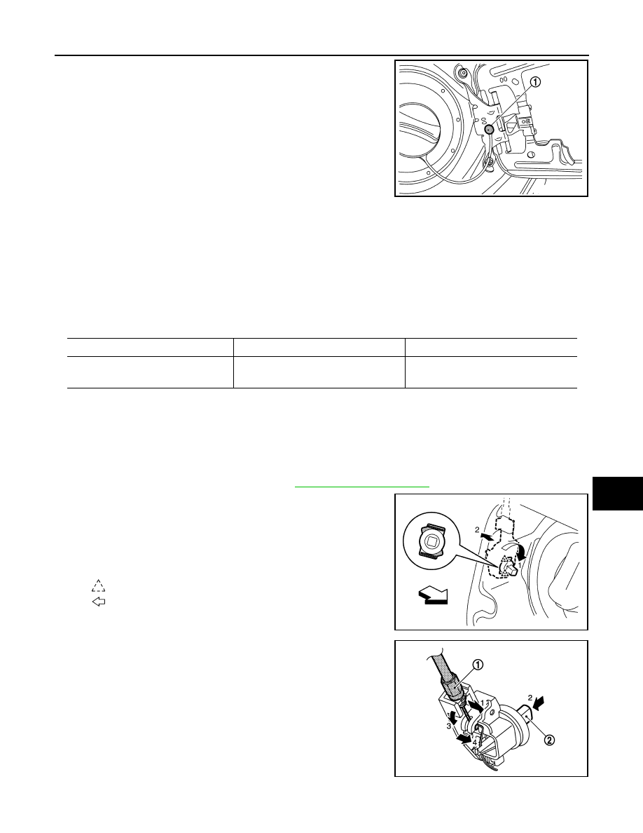
3.
In the order of 1
→
2 as shown in the figure, rotate and disengage
fuel filler lid lock assembly, and then remove fuel filler lid lock
assembly.
NOTE:
Operation is performed easily when rotating fuel filler lid lock
from passenger room side.
4.
In the order of 1
→
4 as shown in the figure. Disengage fuel filler
lid opener cable (1). Remove fuel filler lid opener cable while
pressing stopper pin (2).
JMKIB3183ZZ
Clearance
Evenness
Fuel filler lid – Body side outer
3.7 – 5.3
(0.146 – 0.209)
(-1.0) – (+1.0)
[(-0.039) – (+0.039)]
: Pawl
: Vehicle front
JMKIB1094ZZ
JMKIA5719ZZ