Qashqai J11. Door & Lock - part 11


  Index      Nissan     Qashqai J11. Door & Lock. Service and Repair Manual


Search            copyright infringement  


Content      ..     9      10      11      12     ..


Qashqai J11. Door & Lock - part 11


BACK DOOR

DLK-177

< REMOVAL AND INSTALLATION >

[TYPE 1]

C

D

E

F

G

H

I

J

L

M

A

B

DLK

N

O

P

Note the following items, and install in the reverse order of removal.

CAUTION:

• Check back door hinge rotating part for poor lubrication. Refer to 

DLK-177, "BACK DOOR HINGE :

Inspection"

.

• After installation, perform the fitting adjustment. Refer to 

DLK-174, "BACK DOOR ASSEMBLY :

Adjustment"

.

• After installation, apply touch-up paint (the body color) onto the head of door hinge mounting nuts.

BACK DOOR HINGE : Inspection

INFOID:0000000010434715

Check door hinge rotating part for poor lubrication. Apply body
grease if necessary.

BACK DOOR STAY

BACK DOOR STAY : Removal and Installation

INFOID:0000000010434716

REMOVAL

1.

Support the back door with the suitable material to prevent it from falling.

WARNING:

Bodily injury may occur if no supporting rod is holding the back door open when removing the
back door stay.

CAUTION:

Use protective tape or shop cloth to protect from damage during removal and installation.

2.

Remove back door stay of vehicle body side.
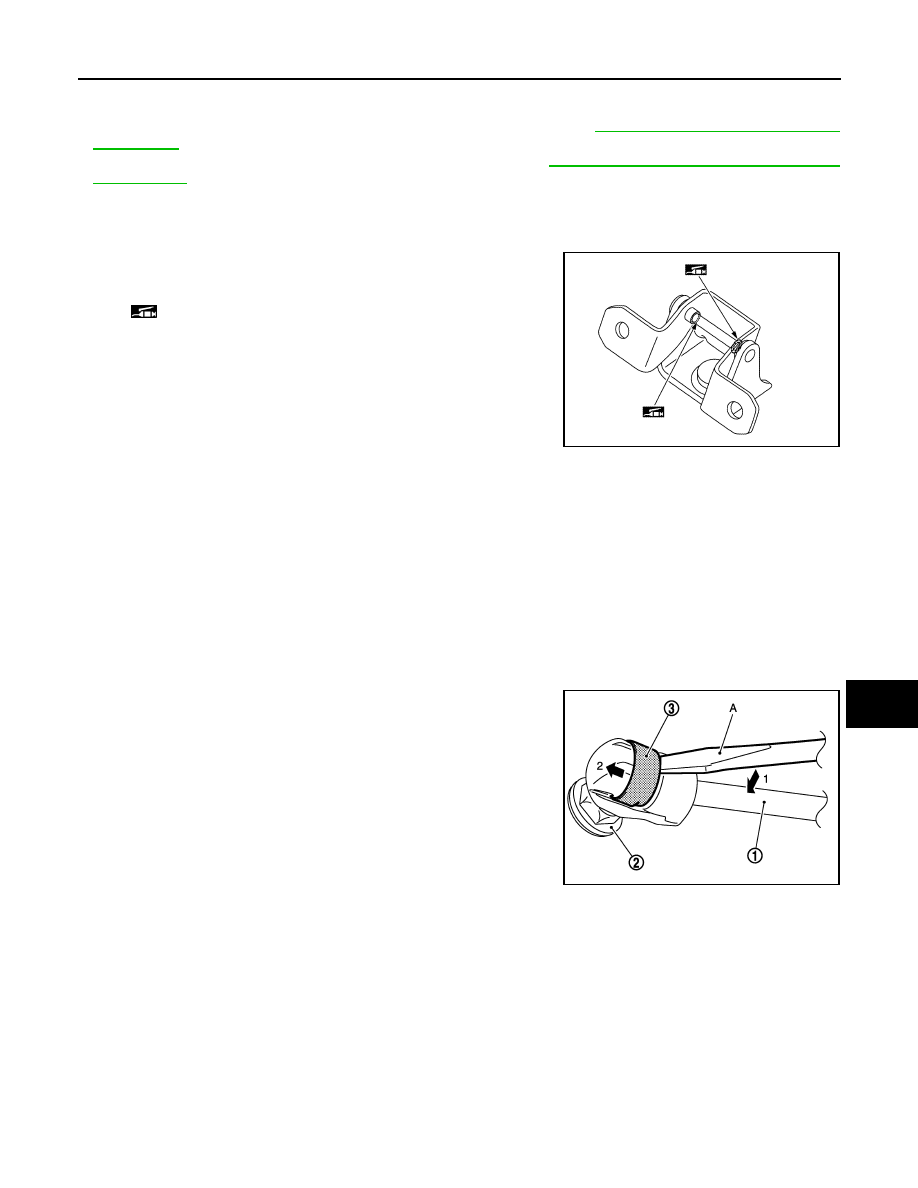
a.

Remove the metal clip (3) located on the connection between
the back door stay (1) and the stud ball (2) by using a remover
tool (A) according to the numerical order 1

2 indicated by

arrows as shown in the figure.

b.

Disengage back door stay from stud ball.

3.

Remove back door stay mounting bolts of back door side, and then remove back door stay.

INSTALLATION

Note the following items, and install in the reverse order of removal.

CAUTION:

• Apply anticorrosive agent onto the mounting surface.
• After installation, check back door open/close, lock/unlock operation.

BACK DOOR STAY : Disposal 

INFOID:0000000010434717

CAUTION:

When performing disposal operation, wear the protective glasses and protective gloves.

: Body grease

JMKIB0628ZZ

JMKIA2255ZZ

DLK-178

< REMOVAL AND INSTALLATION >

[TYPE 1]

BACK DOOR

1.

Fix back door stay (1) using a vise (C)

CAUTION:

When cutting a hole on back door stay, always cover a
hacksaw (A) using a shop cloth (B) to avoid scattering
metal fragments or oil.

2.

Slowly cut a hole and drain the gas in the order of 1

2 as

shown in the figure using a hacksaw at 2 positions of (1) and (2).

BACK DOOR WEATHER-STRIP

BACK DOOR WEATHER-STRIP : Removal and Installation

INFOID:0000000010434718

REMOVAL

Pull up and remove engagement with body from weather-strip joint.

CAUTION:

Never pull strongly on weather-strip.

INSTALLATION

1.

Working from the upper section, align weather-strip center mark with vehicle center position mark and
install weather-strip onto the vehicle.

2.

For the lower section, align the weather-strip seam with center of back door striker.

3.

Pull weather-strip gently to ensure that there is no loose section.

CAUTION:

Securely fit each corner.

JMKIA3336ZZ

A

: 20 mm (0.787 in)

B

: Cat at the groove

JMKIA3609ZZ

HOOD LOCK

DLK-179

< REMOVAL AND INSTALLATION >

[TYPE 1]

C

D

E

F

G

H

I

J

L

M

A

B

DLK

N

O

P

HOOD LOCK

Exploded View

INFOID:0000000010434719

HOOD LOCK

HOOD LOCK : Removal and Installation

INFOID:0000000010434720

REMOVAL

1.

Remove front grille. Refer to 

EXT-26, "Removal and Installation"

.

2.

Remove hood lock assembly mounting bolt and nuts, and then remove hood lock assembly from radiator
core support upper. 

3.

Disconnect hood lock control cable assembly from hood lock assembly.

INSTALLATION

Note the following items, and install in the reverse order of removal.

CAUTION:

• Never bend cable too much, keeping the radius 100 mm (3.937 in) or more.
• After installation, perform hood lock control inspection. Refer to 

DLK-181, "Inspection"

.

1.

Hood lock control handle

2.

Hood lock control cable

3.

Hood safety hook

4.

Hood lock assembly

: Clip

: N·m (kg-m, in-lb)

: N·m (kg-m, ft-lb)

: Body grease

JMKIB3308GB

DLK-180

< REMOVAL AND INSTALLATION >

[TYPE 1]

HOOD LOCK

• Check hood lock assembly for poor lubrication. Refer to 

DLK-181, "Inspection"

.

• After installation, perform hood fitting adjustment. Refer to 

DLK-152, "HOOD ASSEMBLY : Adjust-

ment"

.

HOOD LOCK CONTROL HANDLE

HOOD LOCK CONTROL HANDLE : Removal and Installation

INFOID:0000000010434722

REMOVAL

1.

Remove hood lock control handle mounting bolts, and then remove hood lock control handle.

2.

Disconnect hood lock control cable (2) from hood opener lever
(1) according to the numerical order 1

2 indicated by arrows as

shown in the figure.

3.

Disconnect fuel opener cable from fuel filler lid opener lever of hood lock control handle. Refer to 

DLK-

194, "FUEL FILLER OPENER CABLE : Removal and Installation"

.

INSTALLATION

Install in the reverse order of removal.

HOOD LOCK CONTROL CABLE

HOOD LOCK CONTROL CABLE : Removal and Installation

INFOID:0000000010434721

REMOVAL

1.

Disconnect hood lock control cable from hood lock assembly. Refer to 

DLK-179, "HOOD LOCK : Removal

and Installation"

.

2.

Remove fender protector (driver side). Refer to 

EXT-33, "Removal and Installation"

.

3.

Remove hood lock control cable fixing clips.

4.

Disconnect hood lock control cable from hood lock control handle. Refer to 

DLK-180, "HOOD LOCK

CONTROL HANDLE : Removal and Installation"

.

5.

Remove grommet on the lower dash, and pull the hood lock control cable toward the passenger compart-
ment.

CAUTION:

While pulling, never damage (peeling) the outside of hood lock control cable.

INSTALLATION

Note the following items, and install in the reverse order of removal.

CAUTION:

• Never bend cable too much, keeping the radius 100 mm (3.937 in) or more.
• Check that cable is not offset from the positioning grommet,

and apply the sealant to the grommet (at * mark) properly.

JMKIB0327ZZ

PIIB5801E

HOOD LOCK

DLK-181

< REMOVAL AND INSTALLATION >

[TYPE 1]

C

D

E

F

G

H

I

J

L

M

A

B

DLK

N

O

P

• After installation, perform hood fitting adjustment. Refer to 

DLK-152, "HOOD ASSEMBLY : Adjust-

ment"

.

• After installation, perform hood lock control inspection. Refer to 

DLK-181, "Inspection"

.

HOOD SAFETY HOOK

HOOD SAFETY HOOK : Removal and Installation

INFOID:0000000010478165

REMOVAL

Remove mounting nuts, and then remove hood lock secondary assembly.

INSTALLATION

Note the following item, and install in the reverse order of removal.

CAUTION:

After installation, perform hood lock control inspection. Refer to 

DLK-181, "Inspection"

.

Inspection

INFOID:0000000010434723

NOTE:
If the hood lock cable is bent or deformed, replace it.

1.

Check that hood opener operating is condition 49 N (5.0 kg, 11.0 lb) or below.

2.

Check that secondary latch is securely engaged with secondary striker from the dead load of the hood
assembly.

3.

Check that primary latch is securely engaged with primary striker when hood assembly is closed [free-fall
from approximately 200 mm (7.874 in) height].

CAUTION:

Never free-fall hood assembly from a height of 300 (11.811 in) mm or more.

4.

While operating hood opener, carefully check that the front end of hood is raised by approximately 20.0
mm (0.787 in). Also check that hood opener returns to the original position.

5.

Check that secondary latch is properly engaged with secondary striker [4.0 mm (0.157 in)].

6.

Check the hood lock lubrication condition. If necessary, apply
body grease to hood lock assembly.

: Body grease

JMKIB1164ZZ

DLK-182

< REMOVAL AND INSTALLATION >

[TYPE 1]

FRONT DOOR LOCK

FRONT DOOR LOCK

Exploded View

INFOID:0000000010434724

*

1

: Driver side only

1.

Outside handle escutcheon

2.

Outside handle grip

3.

Front gasket

4.

Inside handle

5.

cable clip

6.

Door lock assembly

7.

Key rod protector*

1

8.

Key rod*

1

9.

TORX bolt

10. Outside handle bracket

11. Rear gasket

: Pawl

: Vehicle front

: Always replace after every disassembly.

: N·m (kg-m, in-lb)

: Body grease

JMKIB3252GB

FRONT DOOR LOCK

DLK-183

< REMOVAL AND INSTALLATION >

[TYPE 1]

C

D

E

F

G

H

I

J

L

M

A

B

DLK

N

O

P

DOOR LOCK

DOOR LOCK : Removal and Installation

INFOID:0000000010434725

REMOVAL

1.

Disconnect inside handle cable from inside handle. Refer to 

DLK-183, "INSIDE HANDLE : Removal and

Installation"

.

2.

Disconnect outside handle cable from outside handle bracket. Refer to 

DLK-183, "OUTSIDE HANDLE :

Removal and Installation"

.

3.

Disconnect door lock assembly harness connector.

4.

Remove door lock assembly screws, and then remove door lock assembly.

INSTALLATION

Note the following items, and install in the reverse order of removal.

CAUTION:

• Never reuse door lock assembly screw. Always replace it with a new one when it is removed.
• Check door lock cable is properly engaged with outside handle bracket.
• When installing key rod, rotate key rod holder until a click is felt.
• Check door lock assembly for poor lubrication. Refer to 

DLK-183, "DOOR LOCK : Inspection"

• Check door open/close, lock/unlock operation after installation. 

DOOR LOCK : Inspection

INFOID:0000000010434726

Check door lock assembly for poor lubrication. Apply body grease if
necessary.

INSIDE HANDLE

INSIDE HANDLE : Removal and Installation

INFOID:0000000010434727

REMOVAL

1.

Remove front door finisher. Refer to 

INT-12, "FRONT DOOR FINISHER : Removal and Installation"

.

2.

Remove inside handle mounting bolt.

3.

Disengage inside handle from door panel while sliding inside handle toward vehicle rear, and then sepa-
rate inside handle.

4.

Disconnect inside handle cable, and then remove inside handle.

INSTALLATION

Note the following item, and install in the reverse order of removal.

CAUTION:

Check door open/close, lock/unlock operation after installation.

OUTSIDE HANDLE

OUTSIDE HANDLE : Removal and Installation

INFOID:0000000010434728

REMOVAL

1.

Fully close the front door glass.

2.

Remove front door finisher. Refer to 

INT-12, "FRONT DOOR FINISHER : Removal and Installation"

.

3.

Remove sealing screen.

: Body grease

JMKIA8534ZZ

DLK-184

< REMOVAL AND INSTALLATION >

[TYPE 1]

FRONT DOOR LOCK

NOTE:
Cut the butyl-tape so that some parts of the butyl-tape do not remain on the sealing screen, if the sealing
screen is reused.

4.

Remove front door glass rear run. Refer to 

GW-23, "Removal and Installation"

.

5.

Remove key rod protector mounting bolts, and then remove key rod protector.

6.

Disengage outside handle cable from cable clip.

7.

Disengage rod holder, and then disconnect key rod from door lock assembly. (Driver side only)

8.

Disconnect outside handle harness connector.

9.

Remove grommet (1) of door side. Loosen, through grommet hole, TORX bolt (2) that fixes outside handle
escutcheon.

10. While pulling outside handle (1)according to the numerical order

1

2 indicated by arrows as shown in the figure, remove outside

handle escutcheon (2).

11. While pulling outside handle (1) according to the numerical order

1

2 indicated by arrows as shown in the figure, slide toward

rear of vehicle to remove outside handle.

12. Remove front gasket (1) and rear gasket (2).

JMKIB0585ZZ

JMKIA0441ZZ

JMKIA2948ZZ

JMKIB2240ZZ

FRONT DOOR LOCK

DLK-185

< REMOVAL AND INSTALLATION >

[TYPE 1]

C

D

E

F

G

H

I

J

L

M

A

B

DLK

N

O

P

13. Slide outside handle bracket toward rear of vehicle to remove.

14. Disconnect outside handle cable (1) from outside handle bracket

(2) according to the numerical order 1

2 indicated by arrows as

shown in the figure.

CAUTION:

Never bend the outside handle cable end.

INSTALLATION

Note the following items, and install in the reverse order of removal.

CAUTION:

• When installing key rod, rotate key rod holder until a click is felt.
• Check that door lock cables are normally engaged with inside handle and outside handle.
• After installation, check door open/close, and lock/unlock operation.

: Pawl

: Vehicle front

: Vehicle front

JMKIA5935ZZ

JMKIA5936ZZ

DLK-186

< REMOVAL AND INSTALLATION >

[TYPE 1]

REAR DOOR LOCK

REAR DOOR LOCK

Exploded View

INFOID:0000000010434729

DOOR LOCK

DOOR LOCK : Removal and Installation

INFOID:0000000010434730

REMOVAL

1.

Remove inside handle. Refer to 

DLK-187, "INSIDE HANDLE : Removal and Installation"

.

2.

Remove outside handle bracket. Refer to 

DLK-187, "OUTSIDE HANDLE : Removal and Installation"

.

1.

Outside handle escutcheon

2.

Outside handle grip

3.

Front gasket

4.

Cable clip

5.

Inside handle

6.

Door lock assembly

7.

TORX bolt

8.

Outside handle bracket

9.

Rear gasket

: Pawl

: Vehicle front

: Always replace after every disassembly.

: N·m (kg-m, in-lb)

: Body grease

JMKIB3254GB

REAR DOOR LOCK

DLK-187

< REMOVAL AND INSTALLATION >

[TYPE 1]

C

D

E

F

G

H

I

J

L

M

A

B

DLK

N

O

P

3.

Remove rear door lower sash mounting bolt, and then remove rear door lower sash.

4.

Disconnect door lock assembly harness connector.

5.

Remove door lock assembly screws, and then remove door lock assembly.

INSTALLATION

Note the following items, and install in the reverse order of removal.

CAUTION:

• Never reuse door lock assembly screw. Always replace it with a new one when it is removed.
• Check door lock cable is properly engaged with outside handle bracket.
• Check door lock assembly for poor lubrication. Refer to 

DLK-187, "DOOR LOCK : Inspection"

• Check door open/close, lock/unlock operation after installation. 

DOOR LOCK : Inspection

INFOID:0000000010434731

Check door lock assembly for poor lubrication. Apply body grease if
necessary.

INSIDE HANDLE

INSIDE HANDLE : Removal and Installation

INFOID:0000000010434732

REMOVAL

1.

Remove rear door finisher. Refer to 

INT-15, "REAR DOOR FINISHER : Removal and Installation"

.

2.

Remove inside handle mounting bolt.

3.

Disengage inside handle from door panel while sliding inside handle toward vehicle rear, and then sepa-
rate inside handle.

4.

Disconnect inside handle cable, and then remove inside handle.

INSTALLATION

Note the following item, and install in the reverse order of removal.

CAUTION:

Check door open/close, lock/unlock operation after installation. 

OUTSIDE HANDLE

OUTSIDE HANDLE : Removal and Installation

INFOID:0000000010434733

REMOVAL

1.

Fully close the rear door glass.

2.

Remove rear door finisher. Refer to 

INT-15, "REAR DOOR FINISHER : Removal and Installation"

.

3.

Remove sealing screen.
NOTE:
Cut the butyl-tape so that some parts of the butyl-tape do not remain on the sealing screen, if the sealing
screen is reused.

: Body grease

JMKIA8534ZZ

DLK-188

< REMOVAL AND INSTALLATION >

[TYPE 1]

REAR DOOR LOCK

4.

Remove grommet (1) of door side. Loosen, through grommet hole, TORX bolt (2) that fixes outside handle
escutcheon.

5.

While pulling outside handle (1) according to the numerical order
1

2 indicated by arrows as shown in the figure, remove outside

handle escutcheon (2).

6.

While pulling outside handle (1) according to the numerical order
1

2 indicated by arrows as shown in the figure, slide toward

rear of vehicle to remove outside handle.

7.

Remove front gasket (1) and rear gasket (2).

JMKIB0588ZZ

JMKIA9526ZZ

JMKIA2948ZZ

: Pawl

: Vehicle front

JMKIB2240ZZ

REAR DOOR LOCK

DLK-189

< REMOVAL AND INSTALLATION >

[TYPE 1]

C

D

E

F

G

H

I

J

L

M

A

B

DLK

N

O

P

8.

Slide outside handle bracket toward rear of vehicle to remove.

9.

Disconnect outside handle cable (1) from outside handle bracket
(2) according to the numerical order 1

2 indicated by arrows as

shown in the figure.

CAUTION:

Never bend the outside handle cable end.

INSTALLATION

Note the following items, and install in the reverse order of removal.

CAUTION:

• Check that door lock cables are normally engaged with inside handle and outside handle.
• After installation, check door open/close, and lock/unlock operation.

: Vehicle front

JMKIA5935ZZ

JMKIA5936ZZ

DLK-190

< REMOVAL AND INSTALLATION >

[TYPE 1]

BACK DOOR LOCK

BACK DOOR LOCK

Exploded View

INFOID:0000000010434734

Removal and Installation

INFOID:0000000010434735

REMOVAL

1.

Remove back door trim finisher lower. Refer to 

INT-31, "Removal and Installation"

.

2.

Disconnect back door lock harness connector.

3.

Remove back door assembly mounting bolts, and then remove back door lock assembly.

INSTALLATION

Note the following items, and install in the reverse order of removal.

CAUTION:

• After installation, check back door open/close, and lock/unlock operation.
• Check door lock assembly for poor lubrication. Refer to 

DLK-191, "Inspection"

.

1.

Back door panel

2.

Back door lock assembly

: N·m (kg-m, ft-lb)

: Body grease

: Indicates that the part is connected at points with same symbol in actual vehicle.

JMKIB3271GB

BACK DOOR LOCK

DLK-191

< REMOVAL AND INSTALLATION >

[TYPE 1]

C

D

E

F

G

H

I

J

L

M

A

B

DLK

N

O

P

Inspection

INFOID:0000000010434736

Check door lock assembly for poor lubrication. Apply body grease if
necessary.

: Body grease

JMKIB0629ZZ

DLK-192

< REMOVAL AND INSTALLATION >

[TYPE 1]

FUEL FILLER LID OPENER

FUEL FILLER LID OPENER

Exploded View

INFOID:0000000010434739

FUEL FILLER LID

FUEL FILLER LID : Removal and Installation

INFOID:0000000010434740

REMOVAL 

1.

Fully open fuel filler lid assembly.

1.

Fuel opener cable

2.

Cable protector

3.

Fuel filler lid lock assembly

4.

Bumper rubber

5.

Fuel filler lid assembly

6.

Fuel filler spring

: Clip

: Pawl

: Always replace after every disassembly.

JMKIB3263ZZ


Content      ..     9      10      11      12     ..