Qashqai J11. Door & Lock - part 10
FRONT FENDER
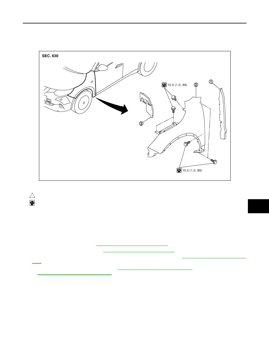
DLK-161
< REMOVAL AND INSTALLATION >
[TYPE 1]
C
D
E
F
G
H
I
J
L
M
A
B
DLK
N
O
P
FRONT FENDER
Exploded View
INFOID:0000000010434689
Removal and Installation
INFOID:0000000010434690
CAUTION:
Use protective tape or shop cloth to protect from damage during removal and installation.
REMOVAL
1.
Remove fillet molding. Refer to
EXT-38, "Removal and Installation"
2.
Remove fender protector. Refer to
EXT-33, "Removal and Installation"
3.
Remove front bumper fascia assembly and bumper side bracket. Refer to
EXT-20, "Removal and Installa-
4.
Remove front combination lamp. Refer to
EXL-319, "Removal and Installation"
EXL-162, "Removal and Installation"
(LED HEADLAMP).
5.
Remove front fender seal.
6.
Remove front fender assembly mounting bolts.
1.
Front fender seal
2.
Front fender assembly
3.
Hoodledge cover
: Pawl
: N·m (kg-m, in-lb)
JMKIB3315GB