Qashqai J11. Driveline - part 9
AWD CONTROL UNIT
DLN-129
< ECU DIAGNOSIS INFORMATION >
[TRANSFER: TY30A]
C
E
F
G
H
I
J
K
L
M
A
B
DLN
N
O
P
ECU DIAGNOSIS INFORMATION
AWD CONTROL UNIT
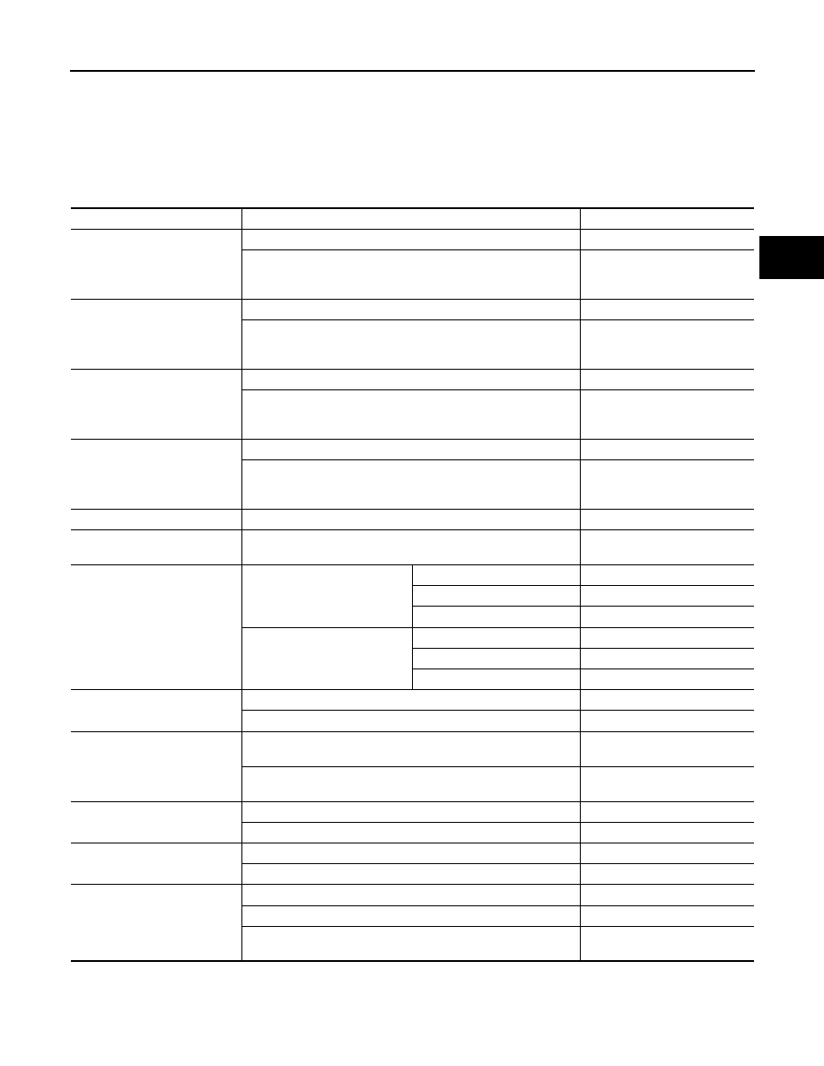
Reference Value
INFOID:0000000010288306
VALUES ON THE DIAGNOSIS TOOL
Monitor item
Condition
Value/Status
FR RH SENSOR
Vehicle stopped
0.00 km/h (0.00 mph)
Vehicle running
CAUTION:
Check air pressure of tire under standard condition.
Approximately equal to the indi-
cation on speedometer (Inside
of
±
10%)
FR LH SENSOR
Vehicle stopped
0.00 km/h (0.00 mph)
Vehicle running
CAUTION:
Check air pressure of tire under standard condition.
Approximately equal to the indi-
cation on speedometer (Inside
of
±
10%)
RR RH SENSOR
Vehicle stopped
0.00 km/h (0.00 mph)
Vehicle running
CAUTION:
Check air pressure of tire under standard condition.
Approximately equal to the indi-
cation on speedometer (Inside
of
±
10%)
RR LH SENSOR
Vehicle stopped
0.00 km/h (0.00 mph)
Vehicle running
CAUTION:
Check air pressure of tire under standard condition.
Approximately equal to the indi-
cation on speedometer (Inside
of
±
10%)
BATTERY VOLT
Always
Battery voltage
THRTL POS SEN
When depressing accelerator pedal
(Value rises gradually in response to throttle position.)
0 – 100%
ETS SOLENOID
Engine running
• At idle speed
AWDAWD mode switch: 2WD
Approx. 0.000 A
AWD indicator lamp: ON
Approx. 0.000 A
LOCK indicator lamp: ON
Approx. 0.000 A
Engine running
• When depressing accelerator
pedal
AWD mode switch: 2WD
Approx. 0.000 A
AWD indicator lamp: ON
R9M: Approx. 0.000 – 2.000 A*
LOCK indicator lamp: ON
R9M: Approx. 2.000 A
STOP LAMP SW
Brake pedal: Depressed
On
Brake pedal: Released
Off
ENG SPEED SIG
Engine stopped
(Engine speed: Less than 400 rpm)
Stop
Engine running
(Engine speed: 400 rpm or more)
Run
ETS ACTUATOR
Engine stopped (Ignition switch: ON)
Off
Engine running
On
4WD WARN LAMP
AWD warning lamp: ON
On
AWD warning lamp: OFF
Off
4WD MODE SW
AWD mode switch: 2WD
2WD
AWD mode switch: AUTO
AUTO
AWD mode switch: LOCK
(State of hold of LOCK position)
LOCK