Qashqai J11. Driveline - part 8
C1204 AWD SOLENOID
DLN-113
< DTC/CIRCUIT DIAGNOSIS >
[TRANSFER: TY30A]
C
E
F
G
H
I
J
K
L
M
A
B
DLN
N
O
P
C1204 AWD SOLENOID
Description
INFOID:0000000010288274
Controls electric controlled coupling by command current from AWD control unit.
DTC Logic
INFOID:0000000010288275
DTC DETECTION LOGIC
DTC CONFIRMATION PROCEDURE
1.
DTC REPRODUCTION PROCEDURE
With CONSULT
1.
Turn the ignition switch OFF to ON.
2.
Perform AWD control unit self-diagnosis.
Is DTC “C1204” detected?
YES
>> Proceed to diagnosis procedure. Refer to
DLN-113, "Diagnosis Procedure"
.
NO
>> INSPECTION END
Diagnosis Procedure
INFOID:0000000010288276
1.
CHECK AWD SOLENOID POWER SUPPLY
1.
Turn the ignition switch OFF.
2.
Disconnect AWD control unit harness connector.
3.
Turn the ignition switch ON.
CAUTION:
Never start the engine.
4.
Check the voltage between AWD control unit harness connector and ground.
Is the inspection result normal?
YES
>> GO TO 2.
NO
>>
Check the following. If any items are damaged, repair or replace damaged parts.
• 10A fuse (#28) open
- Short among 10A fuse (#28) connector, AWD control unit harness connector No. 9 terminal and
the ground
- Open between the battery and AWD control unit harness connector No. 9 terminal
2.
CHECK AWD SOLENOID GROUND
1.
Turn the ignition switch OFF.
2.
Check the continuity between AWD control unit harness connector and ground.
Is the inspection result normal?
YES
>> GO TO 3.
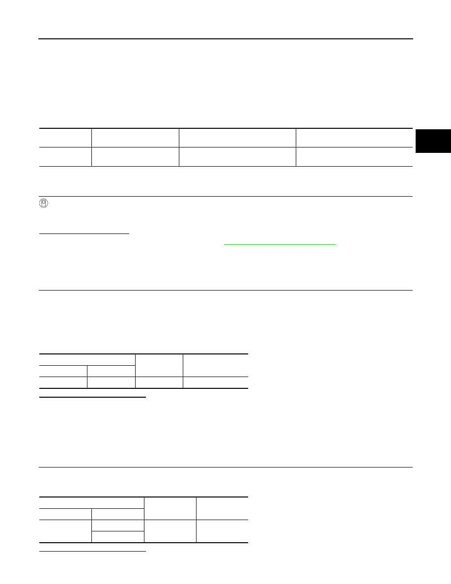
DTC
Items
(CONSULT screen terms)
Diagnostic item is detected when...
Possible cause
C1204
AWDAWD SOLENOID
Malfunction related to AWD solenoid has
been detected.
Internal malfunction of electronic con-
trolled coupling
AWD control unit
Ground
Voltage (Approx.)
Connector
Terminal
B1
9
Ground
Battery voltage
AWD control unit
Ground
Continuity
Connector
Terminal
B1
10
Ground
Existed
11