Qashqai J11. Security control system - part 12
SENSOR CANCEL SWITCH
SEC-177
< DTC/CIRCUIT DIAGNOSIS >
[WITH INTELLIGENT KEY SYSTEM]
C
D
E
F
G
H
I
J
L
M
A
B
SEC
N
O
P
NO
>> Replace sensor cancel switch.
5.
CHECK INTERMITTENT INCIDENT
GI-44, "Intermittent Incident"
.
>> INSPECTION END
Component Inspection
INFOID:0000000010462807
1.
CHECK SENSOR CANCEL SWITCH
1.
Turn ignition switch OFF.
2.
Disconnect sensor cancel switch connector.
3.
Check continuity between sensor cancel switch terminals.
Is the inspection result normal?
YES
>> INSPECTION END
NO
>> Replace sensor cancel switch.
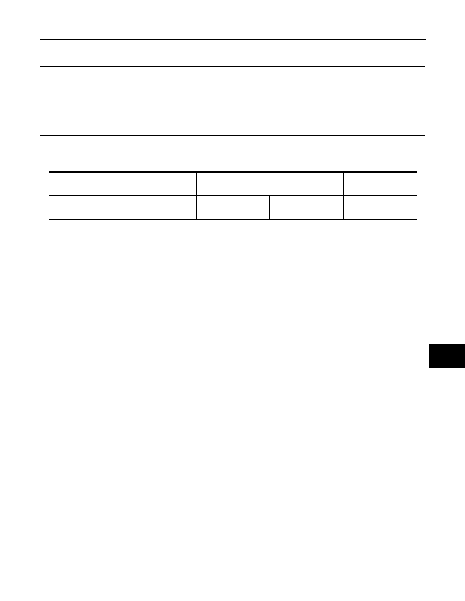
Sensor cancel switch
Condition
Continuity
Terminal
5
6
Sensor cancel switch
Press
Existed
Release
Not existed