Index Nissan Qashqai J11. Lan system. Service and Repair Manual
Search copyright infringement
Content .. 2 3 4 5 ..
Qashqai J11. Lan system - part 4
LAN
CAN SYSTEM
LAN-65
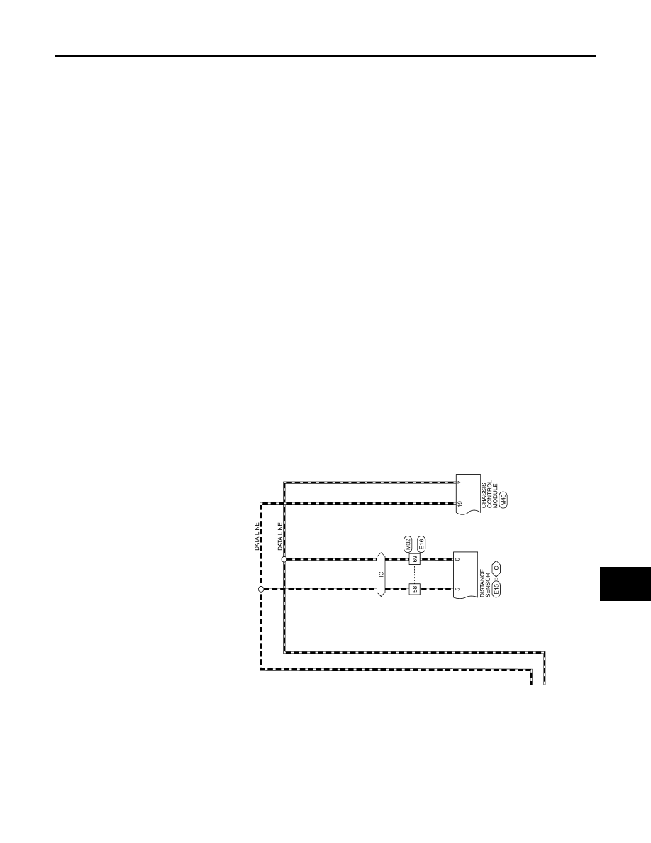
< WIRING DIAGRAM >
[CAN]
C
D
E
F
G
H
I
J
K
L
B
A
O
P
N
JRMWG7358GB