Qashqai J11. Lan system - part 5


  Index      Nissan     Qashqai J11. Lan system. Service and Repair Manual


Search            copyright infringement  


Content      ..     3      4      5      6     ..


Qashqai J11. Lan system - part 5


LAN

ECM BRANCH LINE CIRCUIT

LAN-81

< DTC/CIRCUIT DIAGNOSIS >

[CAN]

C

D

E

F

G

H

I

J

K

L

B

A

O

P

N

ECM BRANCH LINE CIRCUIT

Diagnosis Procedure

INFOID:0000000010272942

1.

CHECK CONNECTOR

1.

Turn the ignition switch OFF.

2.

Disconnect the battery cable from the negative terminal.

3.

Check the terminals and connectors of the ECM for damage, bend and loose connection (unit side and
connector side).

Is the inspection result normal?

YES

>> GO TO 2.

NO

>> Repair the terminal and connector.

2.

CHECK HARNESS FOR OPEN CIRCUIT

1.

Disconnect the connector of ECM.
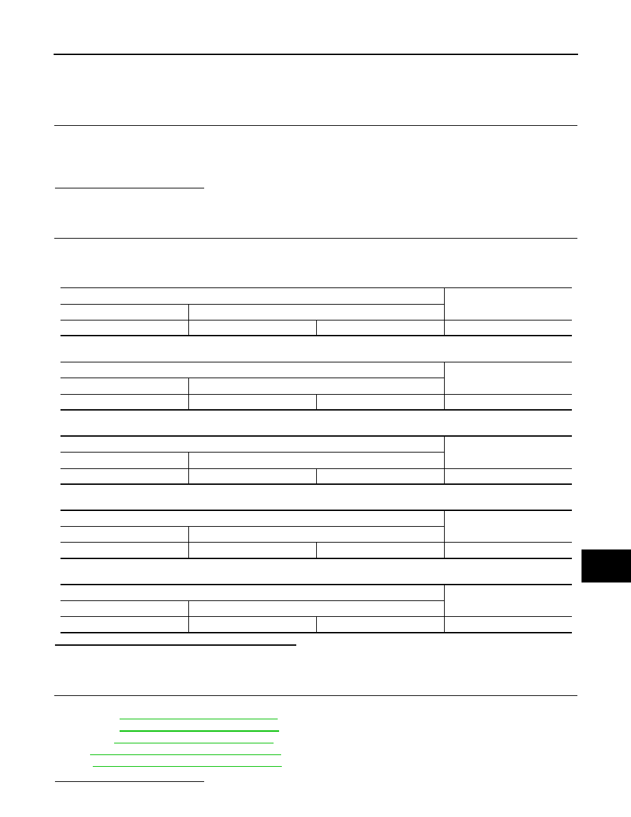
2.

Check the resistance between the ECM harness connector terminals.

-

HR engine models

-

MR16DDT engine models

-

MR20DD engine models

-

K9K engine models

-

R9M engine models

Is the measurement value within the specification?

YES

>> GO TO 3.

NO

>> Repair the ECM branch line.

3.

CHECK POWER SUPPLY AND GROUND CIRCUIT

Check the power supply and the ground circuit of the ECM. Refer to the following.
• HRA2DDT: 

ECH-125, "Diagnosis Procedure"

• MR16DDT: 

ECM-225, "Diagnosis Procedure"

• MR20DD: 

ECM-761, "Diagnosis Procedure"

• K9K: 

ECK-156, "ECM : Diagnosis Procedure"

• R9M: 

EC9-158, "ECM : Diagnosis Procedure"

Is the inspection result normal?

ECM harness connector

Resistance (

)

Connector No.

Terminal No.

E9

1

2

Approx. 108 – 132

ECM harness connector

Resistance (

)

Connector No.

Terminal No.

E61

124

123

Approx. 108 – 132

ECM harness connector

Resistance (

)

Connector No.

Terminal No.

E57

100

99

Approx. 108 – 132

ECM harness connector

Resistance (

)

Connector No.

Terminal No.

E59

1

2

Approx. 108 – 132

ECM harness connector

Resistance (

)

Connector No.

Terminal No.

E58

1

2

Approx. 108 – 132

LAN-82

< DTC/CIRCUIT DIAGNOSIS >

[CAN]

ECM BRANCH LINE CIRCUIT

YES (Present error)>>Replace the ECM. Refer to the following.

• HRA2DDT

ECH-320, "Removal and Installation"

• MR16DDT

ECM-616, "Removal and Installation"

• MR20DD: 

ECM-1031, "Removal and Installation"

• K9K: 

ECK-398, "Removal and Installation"

• R9M: 

EC9-409, "Removal and Installation"

YES (Past error)>>Error was detected in the ECM branch line.
NO

>> Repair the power supply and the ground circuit.

LAN

ABS BRANCH LINE CIRCUIT

LAN-83

< DTC/CIRCUIT DIAGNOSIS >

[CAN]

C

D

E

F

G

H

I

J

K

L

B

A

O

P

N

ABS BRANCH LINE CIRCUIT

Diagnosis Procedure

INFOID:0000000010272945

1.

CHECK CONNECTOR

1.

Turn the ignition switch OFF.

2.

Disconnect the battery cable from the negative terminal.

3.

Check the terminals and connectors of the ABS actuator and electric unit (control unit) for damage, bend
and loose connection (unit side and connector side).

Is the inspection result normal?

YES

>> GO TO 2.

NO

>> Repair the terminal and connector.

2.

CHECK HARNESS FOR OPEN CIRCUIT

1.

Disconnect the connector of ABS actuator and electric unit (control unit).

2.

Check the resistance between the ABS actuator and electric unit (control unit) harness connector termi-
nals.

Is the measurement value within the specification?

YES

>> GO TO 3.

NO

>> Repair the ABS actuator and electric unit (control unit) branch line.

3.

CHECK POWER SUPPLY AND GROUND CIRCUIT

Check the power supply and the ground circuit of the ABS actuator and electric unit (control unit). Refer to

BRC-80, "Diagnosis Procedure"

.

Is the inspection result normal?

YES (Present error)>>Replace the ABS actuator and electric unit (control unit). Refer to 

BRC-142, "Removal

and Installation"

.

YES (Past error)>>Error was detected in the ABS actuator and electric unit (control unit) branch line.
NO

>> Repair the power supply and the ground circuit.

ABS actuator and electric unit (control unit) harness connector

Resistance (

)

Connector No.

Terminal No.

E18

26

14

Approx. 54 – 66

LAN-84

< DTC/CIRCUIT DIAGNOSIS >

[CAN]

IPDM-E BRANCH LINE CIRCUIT

IPDM-E BRANCH LINE CIRCUIT

Diagnosis Procedure

INFOID:0000000010272943

1.

CHECK CONNECTOR

1.

Turn the ignition switch OFF.

2.

Disconnect the battery cable from the negative terminal.

3.

Check the terminals and connectors of the IPDM E/R for damage, bend and loose connection (unit side
and connector side).

Is the inspection result normal?

YES

>> GO TO 2.

NO

>> Repair the terminal and connector.

2.

CHECK HARNESS FOR OPEN CIRCUIT

1.

Disconnect the connector of IPDM E/R.

2.

Check the resistance between the IPDM E/R harness connector terminals.

Is the measurement value within the specification?

YES

>> GO TO 3.

NO

>> Repair the IPDM E/R branch line.

3.

CHECK POWER SUPPLY AND GROUND CIRCUIT

Check the power supply and the ground circuit of the IPDM E/R. Refer to 

PCS-67, "Diagnosis Procedure"

.

Is the inspection result normal?

YES (Present error)>>Replace the IPDM E/R. Refer to 

PCS-68, "Removal and Installation"

.

YES (Past error)>>Error was detected in the IPDM E/R branch line.
NO

>> Repair the power supply and the ground circuit.

IPDM E/R harness connector

Resistance (

)

Connector No.

Terminal No.

E38

24

22

Approx. 54 – 66

LAN

TCM BRANCH LINE CIRCUIT

LAN-85

< DTC/CIRCUIT DIAGNOSIS >

[CAN]

C

D

E

F

G

H

I

J

K

L

B

A

O

P

N

TCM BRANCH LINE CIRCUIT

Diagnosis Procedure

INFOID:0000000010272944

1.

CHECK CONNECTOR

1.

Turn the ignition switch OFF.

2.

Disconnect the battery cable from the negative terminal.

3.

Check the following terminals and connectors for damage, bend and loose connection (unit side and con-
nector side).

-

TCM

-

IPDM E/R

Is the inspection result normal?

YES

>> GO TO 2.

NO

>> Repair the terminal and connector.

2.

CHECK HARNESS FOR OPEN CIRCUIT

1.

Disconnect the following harness connectors.

-

TCM

-

IPDM E/R

2.

Check the continuity between the TCM harness connector and the IPDM E/R harness connector.

-

Except for MR engine models

-

MR engine models

Is the measurement value within the specification?

YES

>> GO TO 3.

NO

>> Repair the branch line between the TCM harness connector and IPDM E/R harness connector

(F89).

3.

CHECK HARNESS FOR OPEN CIRCUIT

Check the resistance between the IPDM E/R terminals.

Is the inspection result normal?

YES

>> GO TO 4.

NO

>> Replace the IPDM E/R. Refer to 

PCS-68, "Removal and Installation"

.

4.

CHECK HARNESS FOR OPEN CIRCUIT

Check the resistance between the IPDM E/R harness connector terminals.

TCM harness connector

IPDM E/R harness connector

Continuity

Connector No.

Terminal No.

Connector No.

Terminal No.

F1

33

F89

71

Existed

23

72

Existed

TCM harness connector

IPDM E/R harness connector

Continuity

Connector No.

Terminal No.

Connector No.

Terminal No.

F2

33

F89

71

Existed

23

72

Existed

IPDM E/R

Continuity

Terminal No.

71

39

Existed

72

40

Existed

LAN-86

< DTC/CIRCUIT DIAGNOSIS >

[CAN]

TCM BRANCH LINE CIRCUIT

Is the measurement value within the specification?

YES

>> GO TO 5.

NO

>> Repair the TCM branch line.

5.

CHECK POWER SUPPLY AND GROUND CIRCUIT

Check the power supply and the ground circuit of the TCM. Refer to the following.
• RE0F10D: 

TM-372, "Diagnosis Procedure"

• RE0F10G: 

TM-609, "Diagnosis Procedure"

• RE0F11A: 

TM-866, "Diagnosis Procedure"

Is the inspection result normal?

YES (Present error)>>Replace the TCM. Refer to the following.

• RE0F10D: 

TM-397, "Removal and Installation"

• RE0F10G: 

TM-632, "Removal and Installation"

• RE0F11A: 

TM-891, "Removal and Installation"

YES (Past error)>>Error was detected in the TCM branch line.
NO

>> Repair the power supply and the ground circuit.

IPDM E/R harness connector

Resistance (

)

Connector No.

Terminal No.

E38

39

40

Approx. 54 – 66

LAN

DLC BRANCH LINE CIRCUIT

LAN-87

< DTC/CIRCUIT DIAGNOSIS >

[CAN]

C

D

E

F

G

H

I

J

K

L

B

A

O

P

N

DLC BRANCH LINE CIRCUIT

Diagnosis Procedure

INFOID:0000000010272947

1.

CHECK CONNECTOR

1.

Turn the ignition switch OFF.

2.

Disconnect the battery cable from the negative terminal.

3.

Check the terminals and connectors of the data link connector for damage, bend and loose connection
(connector side and harness side).

Is the inspection result normal?

YES

>> GO TO 2.

NO

>> Repair the terminal and connector.

2.

CHECK HARNESS FOR OPEN CIRCUIT

Check the resistance between the data link connector terminals.

Is the measurement value within the specification?

YES (Present error)>>Check CAN system type decision again.
YES (Past error)>>Error was detected in the data link connector branch line circuit.
NO

>> Repair the data link connector branch line.

Data link connector

Resistance (

)

Connector No.

Terminal No.

M21

6

14

Approx. 54 – 66

LAN-88

< DTC/CIRCUIT DIAGNOSIS >

[CAN]

EHS/PKB BRANCH LINE CIRCUIT

EHS/PKB BRANCH LINE CIRCUIT

Diagnosis Procedure

INFOID:0000000010339742

1.

CHECK CONNECTOR

1.

Turn the ignition switch OFF.

2.

Disconnect the battery cable from the negative terminal.

3.

Check the terminals and connectors of the electric park brake control unit for damage, bend and loose
connection (unit side and connector side).

Is the inspection result normal?

YES

>> GO TO 2.

NO

>> Repair the terminal and connector.

2.

CHECK HARNESS FOR OPEN CIRCUIT

1.

Disconnect the connector of electric park brake control unit.

2.

Check the resistance between the electric park brake control unit harness connector terminals.

Is the measurement value within the specification?

YES

>> GO TO 3.

NO

>> Repair the electric park brake control unit branch line.

3.

CHECK POWER SUPPLY AND GROUND CIRCUIT

Check the power supply and the ground circuit of the electric park brake control unit. Refer to 

PB-133, "Diag-

nosis Procedure"

.

Is the inspection result normal?

YES (Present error)>>Replace the electric park brake control unit. Refer to 

PB-141, "Removal and Installa-

tion"

.

YES (Past error)>>Error was detected in the electric park brake control unit branch line.
NO

>> Repair the power supply and the ground circuit.

Electric park brake control unit harness connector

Resistance (

)

Connector No.

Terminal No.

M29

16

17

Approx. 54 – 66

LAN

EPS/DAST 3 BRANCH LINE CIRCUIT

LAN-89

< DTC/CIRCUIT DIAGNOSIS >

[CAN]

C

D

E

F

G

H

I

J

K

L

B

A

O

P

N

EPS/DAST 3 BRANCH LINE CIRCUIT

Diagnosis Procedure

INFOID:0000000010272946

1.

CHECK CONNECTOR

1.

Turn the ignition switch OFF.

2.

Disconnect the battery cable from the negative terminal.

3.

Check the terminals and connectors of the EPS control unit for damage, bend and loose connection (unit
side and connector side).

Is the inspection result normal?

YES

>> GO TO 2.

NO

>> Repair the terminal and connector.

2.

CHECK HARNESS FOR OPEN CIRCUIT

1.

Disconnect the connector of EPS control unit.

2.

Check the resistance between the EPS control unit harness connector terminals.

Is the measurement value within the specification?

YES

>> GO TO 3.

NO

>> Repair the EPS control unit branch line.

3.

CHECK POWER SUPPLY AND GROUND CIRCUIT

Check the power supply and the ground circuit of the EPS control unit. Refer to 

STC-36, "Diagnosis Proce-

dure"

.

Is the inspection result normal?

YES (Present error)>>Replace the EPS control unit Refer to 

STC-46, "Removal and Installation"

.

YES (Past error)>>Error was detected in the EPS control unit branch line.
NO

>> Repair the power supply and the ground circuit.

EPS control unit harness connector

Resistance (

)

Connector No.

Terminal No.

M33

2

1

Approx. 54 – 66

LAN-90

< DTC/CIRCUIT DIAGNOSIS >

[CAN]

ESCL BRANCH LINE CIRCUIT

ESCL BRANCH LINE CIRCUIT

Diagnosis Procedure

INFOID:0000000010339744

1.

CHECK CONNECTOR

1.

Turn the ignition switch OFF.

2.

Disconnect the battery cable from the negative terminal.

3.

Check the terminals and connectors of the steering lock unit for damage, bend and loose connection (unit
side and connector side).

Is the inspection result normal?

YES

>> GO TO 2.

NO

>> Repair the terminal and connector.

2.

CHECK HARNESS FOR OPEN CIRCUIT

1.

Disconnect the connector of steering lock unit.

2.

Check the resistance between the steering lock unit harness connector terminals.

Is the measurement value within the specification?

YES

>> GO TO 3.

NO

>> Repair the steering lock unit branch line.

3.

CHECK POWER SUPPLY AND GROUND CIRCUIT

Check the power supply and the ground circuit of the steering lock unit. Refer to 

SEC-166, "STEERING LOCK

UNIT : Diagnosis Procedure"

.

Is the inspection result normal?

YES (Present error)>>Replace the steering lock unit.
YES (Past error)>>Error was detected in the steering lock unit branch line.
NO

>> Repair the power supply and the ground circuit.

Steering lock unit harness connector

Resistance (

)

Connector No.

Terminal No.

M35

3

8

Approx. 54 – 66

LAN

M&A BRANCH LINE CIRCUIT

LAN-91

< DTC/CIRCUIT DIAGNOSIS >

[CAN]

C

D

E

F

G

H

I

J

K

L

B

A

O

P

N

M&A BRANCH LINE CIRCUIT

Diagnosis Procedure

INFOID:0000000010272948

1.

CHECK CONNECTOR

1.

Turn the ignition switch OFF.

2.

Disconnect the battery cable from the negative terminal.

3.

Check the terminals and connectors of the combination meter for damage, bend and loose connection
(unit side and connector side).

Is the inspection result normal?

YES

>> GO TO 2.

NO

>> Repair the terminal and connector.

2.

CHECK HARNESS FOR OPEN CIRCUIT

1.

Disconnect the connector of combination meter.

2.

Check the resistance between the combination meter harness connector terminals.

Is the measurement value within the specification?

YES

>> GO TO 3.

NO

>> Repair the combination meter branch line.

3.

CHECK POWER SUPPLY AND GROUND CIRCUIT

Check the power supply and the ground circuit of the combination meter. Refer to 

MWI-66, "COMBINATION

METER : Diagnosis Procedure"

.

Is the inspection result normal?

YES (Present error)>>Replace the combination meter. Refer to 

MWI-86, "Removal and Installation"

.

YES (Past error)>>Error was detected in the combination meter branch line.
NO

>> Repair the power supply and the ground circuit.

Combination meter harness connector

Resistance (

)

Connector No.

Terminal No.

M52

41

42

Approx. 54 – 66

LAN-92

< DTC/CIRCUIT DIAGNOSIS >

[CAN]

STRG BRANCH LINE CIRCUIT

STRG BRANCH LINE CIRCUIT

Diagnosis Procedure

INFOID:0000000010272950

1.

CHECK CONNECTOR

1.

Turn the ignition switch OFF.

2.

Disconnect the battery cable from the negative terminal.

3.

Check the terminals and connectors of the steering angle sensor for damage, bend and loose connection
(unit side and connector side).

Is the inspection result normal?

YES

>> GO TO 2.

NO

>> Repair the terminal and connector.

2.

CHECK HARNESS FOR OPEN CIRCUIT

1.

Disconnect the connector of steering angle sensor.

2.

Check the resistance between the steering angle sensor harness connector terminals.

Is the measurement value within the specification?

YES

>> GO TO 3.

NO

>> Repair the steering angle sensor branch line.

3.

CHECK POWER SUPPLY AND GROUND CIRCUIT

Check the power supply and the ground circuit of the steering angle sensor. Refer to 

BRC-56, "Wiring Dia-

gram"

.

Is the inspection result normal?

YES (Present error)>>Replace the steering angle sensor. Refer to 

BRC-145, "Removal and Installation"

.

YES (Past error)>>Error was detected in the steering angle sensor branch line.
NO

>> Repair the power supply and the ground circuit.

Steering angle sensor harness connector

Resistance (

)

Connector No.

Terminal No.

M62

5

2

Approx. 54 – 66

LAN

A-BAG BRANCH LINE CIRCUIT

LAN-93

< DTC/CIRCUIT DIAGNOSIS >

[CAN]

C

D

E

F

G

H

I

J

K

L

B

A

O

P

N

A-BAG BRANCH LINE CIRCUIT

Diagnosis Procedure

INFOID:0000000010272951

WARNING:

Always observe the following items for preventing accidental activation.
• Before servicing, turn ignition switch OFF, disconnect battery negative terminal, and wait 3 minutes

or more. (To discharge backup capacitor.)

• Never use unspecified tester or other measuring device.

1.

CHECK CONNECTOR

1.

Turn the ignition switch OFF.

2.

Disconnect the battery cable from the negative terminal.

3.

Check the terminals and connectors of the air bag diagnosis sensor unit for damage, bend and loose con-
nection (unit side and connector side).

Is the inspection result normal?

YES

>> GO TO 2.

NO

>> Replace the main harness.

2.

CHECK AIR BAG DIAGNOSIS SENSOR UNIT

Check the air bag diagnosis sensor unit. Refer to 

SRC-35, "Work Flow"

.

Is the inspection result normal?

YES

>> Replace the main harness.

NO

>> Replace parts whose air bag system has a malfunction.

LAN-94

< DTC/CIRCUIT DIAGNOSIS >

[CAN]

CCM BRANCH LINE CIRCUIT

CCM BRANCH LINE CIRCUIT

Diagnosis Procedure

INFOID:0000000010339745

1.

CHECK CONNECTOR

1.

Turn the ignition switch OFF.

2.

Disconnect the battery cable from the negative terminal.

3.

Check the terminals and connectors of the chassis control module connector for damage, bend and loose
connection (unit side and connector side).

Is the inspection result normal?

YES

>> GO TO 2.

NO

>> Repair the terminal and connector.

2.

CHECK HARNESS FOR OPEN CIRCUIT

1.

Disconnect the connector of chassis control module.

2.

Check the resistance between the chassis control module harness connector terminals.

Is the measurement value within the specification?

YES

>> GO TO 3.

NO

>> Repair the chassis control module branch line.

3.

CHECK POWER SUPPLY AND GROUND CIRCUIT

Check the power supply and the ground circuit of the chassis control module. Refer to 

DAS-320, "Diagnosis

Procedure"

.

Is the inspection result normal?

YES (Present error)>>Replace the chassis control module. Refer to 

DAS-325, "Removal and Installation"

.

YES (Past error)>>Error was detected in the chassis control module branch line.
NG

>> Repair the power supply and the ground circuit.

Chassis control module harness connector

Resistance (

)

Connector No.

Terminal No.

M43

4

3

Approx. 54 – 66

LAN

SONAR BRANCH LINE CIRCUIT

LAN-95

< DTC/CIRCUIT DIAGNOSIS >

[CAN]

C

D

E

F

G

H

I

J

K

L

B

A

O

P

N

SONAR BRANCH LINE CIRCUIT

Diagnosis Procedure

INFOID:0000000010272949

1.

CHECK CONNECTOR

1.

Turn the ignition switch OFF.

2.

Disconnect the battery cable from the negative terminal.

3.

Check the terminals and connectors of the sonar control unit for damage, bend and loose connection (unit
side and connector side).

Is the inspection result normal?

YES

>> GO TO 2.

NO

>> Repair the terminal and connector.

2.

CHECK HARNESS FOR OPEN CIRCUIT

1.

Disconnect the connector of sonar control unit.

2.

Check the resistance between the sonar control unit harness connector terminals.

-

Without parking space measurement

-

With parking space measurement

Is the measurement value within the specification?

YES

>> GO TO 3.

NO

>> Repair the sonar control unit branch line.

3.

CHECK POWER SUPPLY AND GROUND CIRCUIT

Check the power supply and the ground circuit of the sonar control unit. Refer to the following.
• Without parking space measurement: 

SN-46, "Diagnosis Procedure"

• With parking space measurement: 

SN-98, "Diagnosis Procedure"

Is the inspection result normal?

YES (Present error)>>Replace the sonar control unit. Refer to the following.

• Without parking space measurement: 

SN-51, "Removal and Installation"

• With parking space measurement: 

SN-103, "Removal and Installation"

YES (Past error)>>Error was detected in the sonar control unit branch line.
NO

>> Repair the power supply and the ground circuit.

Sonar control unit harness connector

Resistance (

)

Connector No.

Terminal No.

M59

5

6

Approx. 54 – 66

Sonar control unit harness connector

Resistance (

)

Connector No.

Terminal No.

M60

24

23

Approx. 54 – 66

LAN-96

< DTC/CIRCUIT DIAGNOSIS >

[CAN]

4WD BRANCH LINE CIRCUIT

4WD BRANCH LINE CIRCUIT

Diagnosis Procedure

INFOID:0000000010339746

1.

CHECK CONNECTOR

1.

Turn the ignition switch OFF.

2.

Disconnect the battery cable from the negative terminal.

3.

Check the terminals and connectors of the 4WD control unit for damage, bend and loose connection (unit
side and connector side).

Is the inspection result normal?

YES

>> GO TO 2.

NO

>> Repair the terminal and connector.

2.

CHECK HARNESS FOR OPEN CIRCUIT

1.

Disconnect the connector of 4WD control unit.

2.

Check the resistance between the 4WD control unit harness connector terminals.

Is the measurement value within the specification?

YES

>> GO TO 3.

NO

>> Repair the 4WD control unit branch line.

3.

CHECK POWER SUPPLY AND GROUND CIRCUIT

Check the power supply and the ground circuit of the 4WD control unit. Refer to following.
• TY21C: 

DLN-51, "Diagnosis Procedure"

• TY30A: 

DLN-118, "Diagnosis Procedure"

Is the inspection result normal?

YES (Present error)>>Replace the 4WD control unit. Refer to following.

• TY21C: 

DLN-67, "Removal and Installation"

• TY30A: 

DLN-142, "Removal and Installation"

YES (Past error)>>Error was detected in the 4WD control unit branch line.
NG

>> Repair the power supply and the ground circuit.

4WD control unit harness connector

Resistance (

)

Connector No.

Terminal No.

B1

8

16

Approx. 54 – 66


Content      ..     3      4      5      6     ..