Qashqai J11. Heater & Air conditioning Control System - part 10


  Index      Nissan     Qashqai J11. Heater & Air conditioning Control System. Service and Repair Manual


Search            copyright infringement  


Content      ..     8      9      10      11     ..


Qashqai J11. Heater & Air conditioning Control System - part 10


COMPONENT PARTS

HAC-145

< SYSTEM DESCRIPTION >

[MANUAL AIR CONDITIONING]

C

D

E

F

G

H

J

K

L

M

A

B

HAC

N

O

P

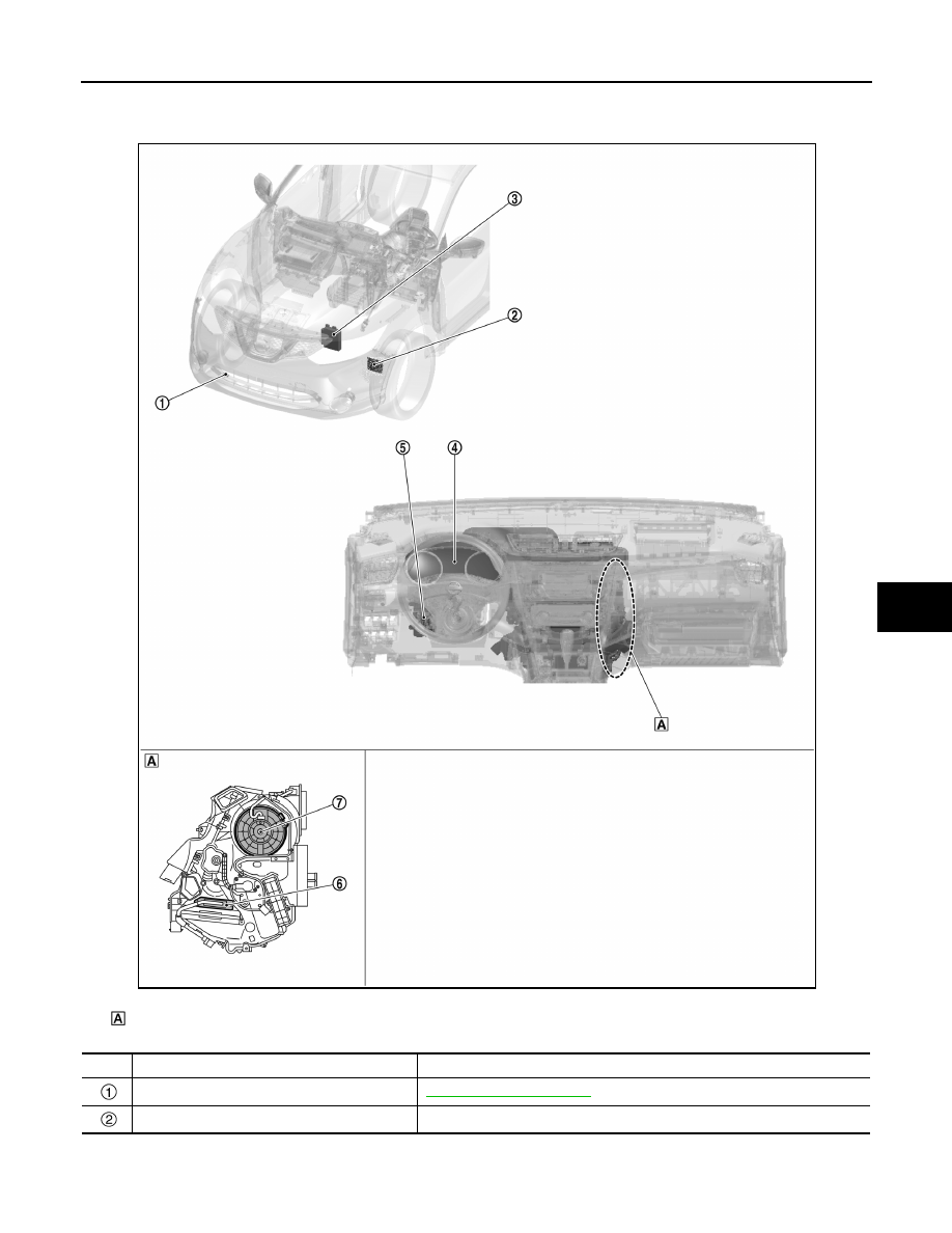
PTC HEATER CONTROL SYSTEM : Component Parts Location

INFOID:0000000010499399

Right side of A/C unit assembly

JMIIA3547ZZ

No.

Component

Function

Ambient sensor

HAC-150, "Ambient Sensor"

PTC relay-1/2/3

PTC relay is controlled by BCM, and supplies power supply to PTC heater.

HAC-146

< SYSTEM DESCRIPTION >

[MANUAL AIR CONDITIONING]

COMPONENT PARTS

A/C UNIT ASSEMBLY

A/C UNIT ASSEMBLY : Intake Sensor

INFOID:0000000010432486

Intake sensor measures evaporator fin temperature. The sensor
uses a thermistor which is sensitive to the change in temperature.
The electrical resistance of the thermistor decreases as temperature
increases.

A/C UNIT ASSEMBLY : Air Mix Door Motor

INFOID:0000000010432487

DESCRIPTION

• The step motor system is adopted for air mix door motor.
• When a drive signal is input from A/C amp. to door motor, a step motor built into the door motor rotates

according to the drive signal, and then stops at the target door position.

• Rotation of motor is transmitted to air mix door by link and lever, then air flow temperature is switched.

AIR MIX DOOR MOTOR DRIVE METHOD

• The 4 drive coils are excited in sequence in order to drive the motor.

ECM

ECM transmits engine speed signal, engine coolant temperature signal, 
cooling fan speed request signal, and electrical power cut freeze signal to 
BCM via CAN communication line.
Refer to 

ECH-13, "Component Parts Location"

 (HR engine models), 

ECM-

25, "ENGINE CONTROL SYSTEM : Component Parts Location"


(MR16DDT engine models), 

ECM-627, "ENGINE CONTROL SYSTEM : 

Component Parts Location"

 (MR20DD engine models), 

ECK-12, "Compo-

nent Parts Location"

 (K9K engine models) or 

EC9-14, "Component Parts Lo-

cation"

 (R9M engine models) for detailed installation location.

Combination meter

Combination meter transmits ambient temperature signal to BCM via CAN 
communication line.

BCM

BCM receives each signals, and controls PTC relay.
BCM transmits idle up signal to ECM according to electrical load condition.
Refer to 

BCS-6, "BODY CONTROL SYSTEM : Component Parts Location"


for detailed installation location.

PTC heater

HAC-149, "A/C UNIT ASSEMBLY : PTC Heater"

Blower motor

HAC-148, "A/C UNIT ASSEMBLY : Blower Motor"

No.

Component

Function

JSIIA1630GB

COMPONENT PARTS

HAC-147

< SYSTEM DESCRIPTION >

[MANUAL AIR CONDITIONING]

C

D

E

F

G

H

J

K

L

M

A

B

HAC

N

O

P

• Direction of rotation is changeable by recomposing pattern of excitation.

A/C UNIT ASSEMBLY : Mode Door Motor

INFOID:0000000010432489

DESCRIPTION

• The step motor system is adopted for mode door motor.
• When a drive signal is input from A/C amp. to door motor, a step motor built into the door motor rotates

according to the drive signal, and then stops at the target door position.

• Rotation of motor is transmitted to mode door (center ventilator and defroster door, sub defroster door, side

ventilator door, and foot door) by link, rod, and lever, then air outlet is switched.

MODE DOOR MOTOR DRIVE METHOD

• The 4 drive coils are excited in sequence in order to drive the motor.
• Direction of rotation is changeable by recomposing pattern of excitation.

A/C UNIT ASSEMBLY : Intake Door Motor

INFOID:0000000010432490

DESCRIPTION

• The step motor system is adopted for intake door motor.
• When a drive signal is input from A/C amp. to door motor, a step motor built into the door motor rotates

according to the drive signal, and then stops at the target door position.

• Rotation of motor is transmitted to intake door by lever, then air inlet is switched.

INTAKE DOOR MOTOR (DRIVER SIDE) DRIVE METHOD

• The 4 drive coils are excited in sequence in order to drive the motor.

JMIIA3574GB

JZIIA0033GB

HAC-148

< SYSTEM DESCRIPTION >

[MANUAL AIR CONDITIONING]

COMPONENT PARTS

• Direction of rotation is changeable by recomposing pattern of excitation.

A/C UNIT ASSEMBLY : Blower Motor

INFOID:0000000010432491

• Brush motor, that rotates coil while brush functions as contact

points, is adopted for blower motor.

• Rotation speed changes according to voltage from power transis-

tor.

A/C UNIT ASSEMBLY : Fan Control Amp.

INFOID:0000000010499376

• Fan control amp., that uses MOS field effect transistor, is adopted

for blower motor speed control.
NOTE:
MOS field effect transistor is a transistor for which the gate portion
is composed of a metal electrode on an oxide layer of semiconduc-
tor. Field effect transistor is controlled by voltage, while ordinary
transistor is controlled by current. Electrode of field effect transistor
is called source, drain, or gate, while electrode of ordinary transis-
tor is called emitter, collector, or base.

• Fan control amp. continuously controls voltage to blower motor,

according to gate voltage from A/C amp.

• This power transistor does not require a HI relay even when the

maximum voltage is applied to blower motor at HI status, because voltage drop is nominal.

JMIIA3565GB

JMIIA3336ZZ

JMIIA0793GB

JMIIA1317ZZ

COMPONENT PARTS

HAC-149

< SYSTEM DESCRIPTION >

[MANUAL AIR CONDITIONING]

C

D

E

F

G

H

J

K

L

M

A

B

HAC

N

O

P

A/C UNIT ASSEMBLY : PTC Heater

INFOID:0000000010521000

• PTC heater is installed on passenger lower side of A/C unit assembly.
• Heat element is heated and air flow temperature is increased by

power supply from PTC relay.

COMPRESSOR

COMPRESSOR : Magnet Clutch

INFOID:0000000010503101

DESCRIPTION

Compressor is driven by the magnet clutch which is magnetized by electric power supply.

STRUCTURE AND OPERATION

• Magnet clutch consists of pulley, clutch disc, and field coil.
- Pulley is connected with crankshaft pulley of engine via drive belt

and is always rotated while engine is running.

- Clutch disc is connected with drive shaft of compressor.
- Field coil, which becomes a strong electric magnet when electricity

is supplied, strongly pulls clutch disc and presses it to pulley.

• When A/C relay integrated in IPDM E/R turns ON, electricity is

supplied to field coil, clutch disc is presses to pulley, and engine
rotational movement is transmitted from crankshaft pulley 

 drive

belt 

 pulley 

 clutch disc 

 drive shaft. Compressor is operated.

When A/C relay turns OFF, electricity is not supplied to field coil,
and clutch disc is released from pulley. Compressor is not oper-
ated.

COMPRESSOR : ECV (Electrical Control Valve)

INFOID:0000000010503102

• ECV (Electrical Control Valve) is integrated in the compressor.

IPDM E/R receives the ECV control signal from A/C amp. via CAN
communication, and ECV is controlled according to the control sig-
nal transmitted from IPDM E/R.

• ECV is controlled according to the control signal transmitted from

IPDM E/R.
The control signal transmitted by IPDM E/R is controlled according
to the ECV control signal transmitted from A/C amp. via CAN com-
munication.

• ECV varies the air pressure balance in the left and right air spaces

that are divided by the swash plate in order to change the angle of
the swash plate inside the compressor.
By changing the swash plate angle, it changes the piston stroke and controls the refrigerant discharge
amount.

JMIIA2397ZZ

JMIIA1767GB

JMIIA3566GB

HAC-150

< SYSTEM DESCRIPTION >

[MANUAL AIR CONDITIONING]

COMPONENT PARTS

A/C Control (A/C Amp.)

INFOID:0000000010499383

A/C control (A/C amp.) controls A/C by calculations based on signals
transmitted from each sensor and switch.
A/C control (A/C amp.) includes a self-diagnosis function. Diagnosis
of the manual air conditioning system can be performed quickly.

Ambient Sensor

INFOID:0000000010503107

Ambient sensor measures ambient air temperature. The sensor
uses a thermistor which is sensitive to the change in temperature.
The electrical resistance of the thermistor decreases as temperature
increases.

Refrigerant Pressure Sensor

INFOID:0000000010499385

DESCRIPTION

• The refrigerant pressure sensor converts high-pressure side refrigerant pressure into voltage and outputs it

to ECM.

• ECM operates cooler cycle protection and cooling fan speed control according to voltage value that is input.

STRUCTURE AND OPERATION

• The refrigerant pressure sensor is a capacitance type sensor. It consists of a pressure detection area and a

signal processing area.

• The pressure detection area, which is a variable capacity condenser, changes internal static capacitance

according to pressure force.

• The signal processing area detects the static capacitance of the pressure detection area, converts the static

capacitance into a voltage value, and transmits the voltage value to ECM.

JMIIA3575ZZ

JMIIA1719GB

PBIB2657E

SYSTEM

HAC-151

< SYSTEM DESCRIPTION >

[MANUAL AIR CONDITIONING]

C

D

E

F

G

H

J

K

L

M

A

B

HAC

N

O

P

SYSTEM

MANUAL AIR CONDITIONING SYSTEM

MANUAL AIR CONDITIONING SYSTEM : System Description

INFOID:0000000010432501

SYSTEM DIAGRAM

DESCRIPTION

• Automatic air conditioning system is controlled by each function of A/C amp.,ECM and IPDM E/R.
• Each operation of air conditioning system can be controlled by A/C control (built-in A/C amp.).
• A/C control switch indicator is turned ON/OFF by air conditioning system operation condition.

CONTROL BY A/C AMP.

HAC-152, "MANUAL AIR CONDITIONING SYSTEM : Air Inlet Control"

HAC-152, "MANUAL AIR CONDITIONING SYSTEM : Compressor Control"

HAC-245, "MANUAL HEATER SYSTEM : Door Control"

HAC-157, "MANUAL AIR CONDITIONING SYSTEM : Cooling Fan Control"

HAC-158, "MANUAL AIR CONDITIONING SYSTEM : Door Motor Starting Position Reset Control"

• Correction for input value

Ambient temperature correction

- A/C amp. inputs the temperature detected by ambient sensor as the ambient temperature. 
- A/C amp. performs the correction of the temperature detected by ambient sensor for air conditioning control. 
- A/C amp. selects and uses the initial value of ambient temperature data depending on the engine coolant

temperature when turning the ignition switch from OFF to ON. The detection temperature of the ambient

JMIIA3576GB

HAC-152

< SYSTEM DESCRIPTION >

[MANUAL AIR CONDITIONING]

SYSTEM

sensor is used when engine coolant temperature is low [less than approximately 56

°

C (133

°

F)]. The mem-

ory data (before the ignition switch is OFF) when the engine is warmed up [approximately 56

°

C (133

°

F) or

more]. 

- The correction of the ambient temperature is not performed when the detection temperature of the ambient

temperature is less than approximately 

20

°

C (–4

°

F). 

Intake temperature correction

- A/C amp. inputs the temperature detected by intake sensor as the intake temperature (evaporator tempera-

ture).

- A/C amp. performs the correction of the temperature detected by intake sensor for air conditioning control. 
- A/C amp. performs the correction so that the recognition intake temperature changes depending on the dif-

ference between the detected intake temperature and the recognition intake temperature. If the difference is
large, the changing is early. The changing becomes slow as the difference becomes small. 

CONTROL BY ECM

HAC-152, "MANUAL AIR CONDITIONING SYSTEM : Compressor Control"

CONTROL BY IPDM E/R

HAC-152, "MANUAL AIR CONDITIONING SYSTEM : Compressor Control"

MANUAL AIR CONDITIONING SYSTEM : Air Inlet Control

INFOID:0000000010432505

DESCRIPTION

• A/C amp. controls the intake door motor and switches the air inlets.
• A/C amp. controls the air inlets so that they are set to fresh air intake, when compressor is stopped by low

temperature protection control.

• When the following conditions are met, A/C amp. controls the air inlets to 20% recirculation. (However, this

does not occur when high water temperature control is in effect.)
At this time, the intake switch indicator lamp turns OFF.

- Fan control dial: 21st - 24th
- Temperature control dial: Full hot
- Air outlet mode: DF ON or DEF ON

HIGH ENGINE COOLANT TEMPERATURE CONTROL

When either of the following conditions is met, A/C amp. changes the air inlets to recirculation.

Condition 1

• Air outlet: Other than D/F or DEF
• A/C switch: ON
• Ambient temperature: More than 25

°

C (77

°

F)

• Vehicle speed: 30 km/h or more
• Engine coolant temperature: 105

°

C (221

°

F) or more

Condition 2

• Air outlet: D/F or DEF
• Air inlet: Fresh air intake
• A/C switch: ON
• Ambient temperature: More than 25

°

C (77

°

F)

• Vehicle speed: 30 km/h or more
• Engine coolant temperature: 105

°

C (221

°

F) or more

MANUAL AIR CONDITIONING SYSTEM : Compressor Control

INFOID:0000000010432506

DESCRIPTION

• When the compressor activation condition is satisfied while blower motor is activated, A/C amp. transmits A/

C ON signal and blower fan ON signal to ECM.

• ECM judges the conditions of each sensor (Refrigerant pressure sensor signal, accelerator position signal,

etc.), and transmits the A/C compressor request signal to IPDM E/R via CAN communication line.

• By receiving the A/C compressor request signal from ECM, IPDM E/R turns the A/C relay to ON, and acti-

vates the compressor. Refer to 

PCS-7, "RELAY CONTROL SYSTEM : System Description"

.

CONTROL BY A/C AMP.

Low Temperature Protection Control

SYSTEM

HAC-153

< SYSTEM DESCRIPTION >

[MANUAL AIR CONDITIONING]

C

D

E

F

G

H

J

K

L

M

A

B

HAC

N

O

P

When intake sensor detects that evaporator fin temperature is 

 [

5.0

°

C (23.0

°

F)] or less, A/C amp. requests ECM to turn the compres-

sor OFF, and stops the compressor.
When the air temperature returns to 

 [1.0

°

C (33.8

°

F)] or more, the

compressor is activated.

Refrigerant Discharge Amount Control

• A/C amp. transmits the ECV control signal via CAN communication. IPDM E/R transmits the control signal to

ECV according to the received ECV control signal.

• ECV is controlled according to change in the duty ratio of the transmitted control signal.
• Except when temperature setting is full cold or outlet is DEF, A/C amp. controls the refrigerant discharge

amount according to the required cooling capacity.

• A/C amp. increases the refrigerant discharge amount when evaporator temperature is higher than the target

temperature upper limit, and reduces the refrigerant discharge amount when evaporator temperature is at or
below the target temperature upper limit.

NOTE:
Target temperature upper limit value of evaporator can be changed using “TARGET EVAPORATOR TEMP
UPPER LIMIT SETTING” in “WORK SUPPORT” mode of CONSULT. Refer to 

HAC-191, "Setting of Target

Evaporator Temperature Upper Limit Value"

.

Compressor Oil Circulation Control

When the engine starts, A/C amp. activates the compressor for a few seconds and circulates the compressor
oil once.

CONTROL BY ECM

Compressor Protection Control at Pressure Malfunction

When the high-pressure side value that is detected by refrigerant pressure sensor is as per the following state,
ECM requests IPDM E/R to turn A/C relay OFF and stops the compressor.
• 3.12 MPa (31.82 kg/cm

2

, 452.4 psi) or more (When the engine speed is less than 1,500 rpm)

• 2.74 MPa (27.95 kg/cm

2

, 397.3 psi) or more (When the engine speed is 1,500 rpm or more)

• 0.14 MPa (1.43 kg/cm

2

, 20.3 psi) or less

Air Conditioning Cut Control

When the engine condition is high load, ECM transmit A/C relay OFF request to IPDM E/R, and stops the
compressor.

MANUAL AIR CONDITIONING SYSTEM : Door Control

INFOID:0000000010432507

SWITCH AND THEIR CONTROL FUNCTION

JMIIA2550GB

HAC-154

< SYSTEM DESCRIPTION >

[MANUAL AIR CONDITIONING]

SYSTEM

*1: With rear ventilator
*2: With rear foot duct
NOTE:
The sub-defroster and side ventilator door include a permanent opening and does not fully close.

Intake door

Blower motor

Air conditioner filter

Evaporator

Heater core

PTC heater

Air mix door

Foot door

Side ventilator door

Sub defroster door

Center ventilator and defroster door

Fresh air

Recirculation air

Discharge air

Defroster

Center ventilator

Side ventilator

Rear ventilator

*1

Front foot

Rear foot

*2

JMIIA3570ZZ

SYSTEM

HAC-155

< SYSTEM DESCRIPTION >

[MANUAL AIR CONDITIONING]

C

D

E

F

G

H

J

K

L

M

A

B

HAC

N

O

P

For Europe and Russia

Except for Europe and Russia

Switch/dial position

Door position

Mode door

Intake door

Air mix 

door

Ce

nt

e

r v

e

n

til

at

o

r a

n

d

 de

fr

ost

e

do

or

S

u

b

 de

fros

te

r do

or

Si

de

 v

e

n

til

at

o

do

or

Fo

ot doo

r

• MODE VENT switch
• MODE FOOT switch
• MODE DEF switch
• MAX DEF switch

MODE 
position

VENT/DEF (V/D)

VENT

Bi-level (B/L)

ALL

FOOT

DEF/FOOT (D/F)

DEF

INTAKE switch

REC

FRE

Temperature control dial

Full cold

Full cold – Full hot

 - 

Full hot

Switch/dial position

Door position

Mode door

Intake 

door

Air mix 

door

Ce

nt

er v

e

n

til

ato

r a

n

d

 de

fros

te

r do

or

Sub

 de

fr

ost

e

r do

or

S

ide

 v

e

n

til

ato

r do

or

Fo

ot

 do

o

r

VENT switch

B/L switch

FOOT switch

D/F switch

DEF switch

HAC-156

< SYSTEM DESCRIPTION >

[MANUAL AIR CONDITIONING]

SYSTEM

AIR DISTRIBUTION

Without rear ventilator, without rear foot

*: These positions are applied only to models for Europe and Russia.

Without rear ventilator, with rear foot

INTAKE switch

REC

FRE

Temperature control dial

Full cold

Full cold – Full hot

 – 

Full hot

Discharge air flow

MODE position

Air outlet/distribution

Ventilator

Front foot

Defroster

Center

Side

V/D*

40%

35%

25%

VENT

54%

46%

B/L

31%

40%

29%

ALL*

21%

34%

31%

14%

FOOT

10%

58%

32%

D/F

9%

43%

48%

DEF

10%

90%

Switch/dial position

Door position

Mode door

Intake 

door

Air mix 

door

Ce

nte

r v

e

n

tila

to

r an

de

fros

te

r do

or

Su

b de

fr

os

te

r do

or

Si

de

 ve

nt

ila

to

r do

or

Fo

ot

 do

or

Discharge air flow

MODE position

Air outlet/distribution

Ventilator

Foot

Defroster

Center

Side

Front

Rear

V/D

40%

35%

25%

VENT

54%

46%

B/L

33%

40%

16%

11%

ALL

22%

35%

16%

11%

16%

FOOT

11%

32%

25%

32%

D/F

8%

24%

19%

49%

DEF

10%

90%

SYSTEM

HAC-157

< SYSTEM DESCRIPTION >

[MANUAL AIR CONDITIONING]

C

D

E

F

G

H

J

K

L

M

A

B

HAC

N

O

P

With rear ventilator, with rear foot

MANUAL AIR CONDITIONING SYSTEM : Cooling Fan Control

INFOID:0000000010519431

DESCRIPTION

A/C amp. controls the cooling fan operation request according to the refrigerant pressure status and vehicle
speed status.
NOTE:
For an overview of the cooling fan and information about control, refer to 

ECH-33, "COOLING FAN CONTROL

: System Description"

 (HR engine models), 

ECM-74, "COOLING FAN CONTROL : System Description"

(MR16DDT engine models), 

ECM-654, "COOLING FAN CONTROL : System Description"

 (MR20DD engine

models) 

ECK-34, "COOLING FAN CONTROL : System Description"

 (K9K engine models) or 

EC9-37, "COOL-

ING FAN CONTROL : System Description"

 (R9M engine models).

CONTROL OUTLINE

• A/C amp. receives the refrigerant pressure sensor signal from ECM via CAN communication, and the vehi-

cle speed signal from the combination meter via CAN communication.

• A/C amp. sets one of the optionally determined stages according to the received refrigerant pressure sensor

signal and vehicle speed signal.
NOTE:
For the rules that prescribe the predetermined stages, refer to the following figures.
• Vehicle speed stages

Vehicle speed [Km/h (MPH)]

-

: 12 (7.5)

-

: 20 (12)

-

: 72 (45)

-

: 80 (50)

• Refrigerant pressure stages (for Europe and Russia)

Refrigerant pressure [MPa (bar, kg/cm

2

, psi)]

-

: 0.7 (7, 7.14, 102)

-

: 1.0 (10, 10.2, 145)

-

: 1.28 (12.8, 13.1, 186)

-

: 1.58 (15.8, 16.1, 229)

-

: 1.88 (18.8, 19.2, 273)

-

: 2.08 (20.8, 21.2, 302)

Discharge air flow

MODE position

Air outlet/distribution

Ventilator

Foot

Defroster

Front

Rear

Front

Rear

Center

Side

V/D

39%

27%

11%

23%

VENT

47%

38%

15%

B/L

25%

34%

13%

18%

10%

ALL

21%

27%

11%

20%

10%

11%

FOOT

7%

4%

38%

24%

27%

D/F

6%

2%

30%

17%

45%

DEF

8%

2%

90%

JMIIA3568GB

JMIIA3569GB

HAC-158

< SYSTEM DESCRIPTION >

[MANUAL AIR CONDITIONING]

SYSTEM

• Refrigerant pressure stages (except for Europe and Russia)

Refrigerant pressure [MPa (bar, kg/cm

2

, psi)]

-

: 0.7 (7, 7.14, 102)

-

: 1.0 (10, 10.2, 145)

-

: 1.08 (10.8, 11.0, 157)

-

: 1.38 (13.8, 14.1, 200)

-

: 1.68 (168, 17.1, 244)

• The requested cooling fan operation strength (0%, 40%, 100%%) is determined as shown in the following

table according to the combination of these two stages, and the request signal is transmitted to ECM via
CAN communication.

Cooling fan operation strength

Unit: %

MANUAL AIR CONDITIONING SYSTEM : Door Motor Starting Position Reset Control

INFOID:0000000010519452

• Step motors are used for the mode door motor air mix door motor, and intake door motor.
• Because the step motors do not have position detection mechanisms, there may be a deviation between the

door position recognized by A/C amp. and the actual door position.
Therefore, A/C amp. performs motor zero position reset for aligning its recognized door position with the
actual door position.

• The reset signal is transmitted from A/C amp. to the air mix door motor, mode door motor, and intake door

motor, which then perform zero position reset.

• After any of the following conditions is met, A/C amp. performs motor zero position reset when the ignition

switch is next turned ON.

- The ignition switch is turned from ON to OFF a total of 360 times.
- The ignition switch turns OFF while the mode door motor, air mix door motor, or intake door motor is operat-

ing.

• If A/C amp., air mix door motor, mode door motor, or intake door motor is removed, it is necessary to perform

motor zero position reset using CONSULT.

PTC HEATER CONTROL SYSTEM

JMIIA3577GB

Refrigerant pressure stages

1

2

3

4

Vehicle speed stag-
es

1

40

40

100

100

2

40

40

100

100

3

0

0

0

100

SYSTEM

HAC-159

< SYSTEM DESCRIPTION >

[MANUAL AIR CONDITIONING]

C

D

E

F

G

H

J

K

L

M

A

B

HAC

N

O

P

PTC HEATER CONTROL SYSTEM : System Description

INFOID:0000000010502884

SYSTEM DIAGRAM

DESCRIPTION

• BCM performs PTC relay ON/OFF control based on engine speed, engine coolant temperature, electrical

power cut freeze signal (permission signal, retention signal, stop signal), blower motor operation state sig-
nal, front window defogger state signal, ambient temperature signal, battery voltage, and electrical load state
(high beam request, low beam request, and others).

• When PTC relay turns ON, power supply is supplied to PTC heater. Heating element is heated and air flow

temperature is increased. Heating is available for a period of time until engine coolant temperature is
increased when engine starts cold in cold climate.

• Idle up request signal is transmitted from BCM to ECM while PTC heater operates. Idle speed is increased,

warming-up is facilitated, and battery electric power is obtained.

• Electric power supplied to PTC heating element is subject to PTC relay control conditions. 

NOTE:
PTC heater operation depends on ambient temperature and battery voltage. PTC heater is ON when ambient
temperature is 8

°

C or less. PTC heater is OFF when ambient temperature is 12

°

C (53.6

°

F) or more. PTC

heater is ON when battery voltage is 11.5 V or more. PTC heater is OFF when battery voltage is 11 V or less.

JMIIA3583GB

PTC heater

Operation

PTC relay-1

PTC relay-2

PTC relay-3

Electric power (W)

OFF

OFF

OFF

OFF

OFF

Approx. 0

PTC heater-1

LOW

ON

OFF

OFF

Approx. 333

PTC heater-2

MID

ON

ON

OFF

Approx. 666

PTC heater-3

HI

ON

ON

ON

Approx. 999

HAC-160

< SYSTEM DESCRIPTION >

[MANUAL AIR CONDITIONING]

OPERATION

OPERATION

Switch Name and Function

INFOID:0000000010432511

OPERATION AND DISPLAY OF AUTOMATIC AIR CONDITIONING SYSTEM (FOR EUROPE AND
RUSSIA)

Operation: A/C control

INTAKE switch

A/C switch

MAX DEF switch

Fan control dial

MODE DEF switch

MODE VENT switch

MODE FOOT switch

Temperature control dial

Switch name

Function

INTAKE switch

Air inlet changes between recirculation (REC) 

 fresh air intake (FRE) each time this switch is pressed.

• Switch indicator lamp ON: Recirculation
• Switch indicator lamp OFF: Fresh air intake

A/C switch

Compressor control (switch indicator) changes between ON 

 OFF each time this switch is pressed 

while blower motor is operated.
NOTE:
A/C switch cannot be turned ON when blower motor is OFF.

MAX DEF switch

MAX DEF mode (switch indicator) changes between ON 

 OFF each time switch is pressed.

• Air conditioning becomes the following status when MAX DEF mode is turned ON.
- Air outlet: DEF
- Air flow: ON
- Air inlet: Fresh air intake
- A/C switch: ON
• Air conditioning becomes the following status when MAX DEF mode is turned OFF.
- Air outlet: Settings set before DEF mode is turned ON
- Air flow: Settings set before DEF mode is turned ON
- Air inlet: Settings set before DEF mode is turned ON
- A/C switch: Settings set before DEF mode is turned ON

Fan control dial

The air flow can be manually set within the range of speeds 1st - 24th by operating the dial.

JMIIA3578ZZ


Content      ..     8      9      10      11     ..