Qashqai J11. Heater & Air conditioning Control System - part 8


  Index      Nissan     Qashqai J11. Heater & Air conditioning Control System. Service and Repair Manual


Search            copyright infringement  


Content      ..     6      7      8      9     ..


Qashqai J11. Heater & Air conditioning Control System - part 8


BLOWER MOTOR

HAC-113

< DTC/CIRCUIT DIAGNOSIS >

[AUTOMATIC AIR CONDITIONING]

C

D

E

F

G

H

J

K

L

M

A

B

HAC

N

O

P

YES

>> GO TO 2.

NO

>> Replace blower motor. Refer to 

VTL-17, "Removal and Installation"

.

2.

CHECK BLOWER MOTOR-II

Check that there is not breakage or damage in the blower motor. 

Is the inspection result normal?

YES

>> GO TO 3.

NO

>> Replace blower motor. Refer to 

VTL-17, "Removal and Installation"

.

3.

CHECK BLOWER MOTOR-III

Check that blower motor turns smoothly. 

Is the inspection result normal?

YES

>> INSPECTION END

NO

>> Replace blower motor. Refer to 

VTL-17, "Removal and Installation"

.

Component Inspection (Blower Relay)

INFOID:0000000010432237

1.

CHECK BLOWER RELAY

1.

Remove blower relay. Refer to 

PG-104, "Fuse, Connector and Terminal Arrangement"
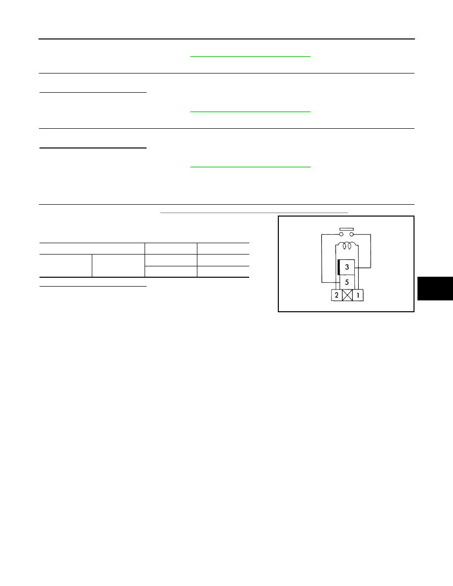
2.

Check continuity between blower relay terminal 3 and 5 when
the voltage is supplied between terminal 1 and 2. 

Is the inspection result normal?

YES

>> INSPECTION END

NO

>> Replace blower relay.

Terminal

Voltage

Continuity

3

5

ON

Existed

OFF

Not existed

JSIIA1551ZZ

HAC-114

< DTC/CIRCUIT DIAGNOSIS >

[AUTOMATIC AIR CONDITIONING]

MAGNET CLUTCH

MAGNET CLUTCH

Component Function Check

INFOID:0000000010432238

1.

CHECK MAGNET CLUTCH OPERATION

CONSULT ACTIVE TEST

1.

Select “COMPRESSOR” of IPDM E/R active test item.

2.

With operating the test item, check magnet clutch operation by listening and viewing.

Does it operate normally?

YES

>> INSPECTION END

NO

>> Refer to 

HAC-114, "Diagnosis Procedure"

.

Diagnosis Procedure

INFOID:0000000010432239

1.

CHECK MAGNET CLUTCH

CONSULT

1.

Turn ignition switch OFF

2.

Disconnect compressor connector. 

3.

Select “COMPRESSOR” of IPDM E/R active test item.

4.

With operating the test item, check Check voltage between compressor harness connector and ground.

Does it operate normally?

YES

>> GO TO 4.

NO

>> GO TO 2.

2.

CHECK FUSE

1.

Turn ignition switch OFF

2.

Check 15 A fuse (No. 57, located in IPDM E/R).
NOTE:
Refer to 

PG-109, "Fuse, Connector and Terminal Arrangement"

Is the inspection result normal?

YES

>> GO TO 3.

NO

>> Replace the blown fuse after repairing the affected circuit if a fuse is blown. 

3.

CHECK MAGNET CLUTCH POWER SUPPLY CIRCUIT FOR OPEN

1.

Disconnect IPDM E/R connector.

2.

Check continuity between IPDM E/R harness connector and compressor harness connector. 

Is the inspection result normal?

YES

>> Replace IPDM E/R. Refer to 

PCS-68, "Removal and Installation"

.

NO

>> Repair harness or connector. 

4.

CHECK MAGNET CLUTCH GROUND CIRCUIT FOR OPEN

Check continuity between compressor harness connector and ground. 

+

Condition

Voltage

Compressor

Connector

Terminal

F6

1

Ground

Active test: COM-
PRESSOR

Off

0 - 0.1 V

On

11 - 14 V

IPDM E/R

Compressor

Continuity

Connector

Terminal

Connector

Terminal

F90

95

F6

1

Existed

MAGNET CLUTCH

HAC-115

< DTC/CIRCUIT DIAGNOSIS >

[AUTOMATIC AIR CONDITIONING]

C

D

E

F

G

H

J

K

L

M

A

B

HAC

N

O

P

Is the inspection result normal?

YES

>> Replace compressor. Refer to 

HA-31, "Removal and Installation"

 (HRA2DDT and MR16DDT

engine models for Europe), 

HA-75, "Removal and Installation"

. (K9K and R9M engine models for

Europe), 

HA-122, "Removal and Installation"

 (HRA2DDT, MR16DDT and MR20DD engine mod-

els except for Europe) or 

HA-171, "Removal and Installation"

. (K9K and R9M engine models

except for Europe).

NO

>> Repair harness or connector. 

Compressor

Continuity

Connector

Terminal

F6

2

Ground

Existed

HAC-116

< DTC/CIRCUIT DIAGNOSIS >

[AUTOMATIC AIR CONDITIONING]

ECV (ELECTRICAL CONTROL VALVE)

ECV (ELECTRICAL CONTROL VALVE)

Diagnosis Procedure

INFOID:0000000010432240

1.

CHECK ECV POWER SUPPLY CIRCUIT

1.

Turn ignition switch OFF.

2.

Disconnect compressor connector.

3.

Turn ignition switch ON.

4.

Check voltage between compressor harness connector and ground.

Except for HR engine models with CVT, MR16DDT engine models, R9M engine models for EURO3 and models for Korea

HR engine models with CVT, MR16DDT engine models, R9M engine models for EURO3 and models for Korea

Is the inspection result normal?

YES

>> GO TO 3.

NO

>> GO TO 2.

2.

CHECK ECV POWER SUPPLY CIRCUIT FOR OPEN

1.

Turn ignition switch OFF.

2.

Disconnect IPDM E/R connector.

3.

Check continuity between compressor harness connector and IPDM E/R harness connector.

Except for HR engine models with CVT, MR16DDT engine models, R9M engine models for EURO3 and models for Korea

HR engine models with CVT, MR16DDT engine models, R9M engine models for EURO3 and models for Korea

Is the inspection result normal?

YES

>> Replace IPDM E/R. Refer to 

PCS-68, "Removal and Installation"

.

NO

>> Repair harness or connector.

3.

CHECK ECV CONTROL SIGNAL CIRCUIT FOR OPEN

1.

Turn ignition switch OFF.

2.

Disconnect IPDM E/R connector.

3.

Check continuity between compressor harness connector and IPDM E/R harness connector.

Except for HR engine models with CVT, MR16DDT engine models, R9M engine models for EURO3 and models for Korea

+

Voltage

Compressor

Connector

Terminal

F151

3

Ground

11 - 14 V

+

Voltage

Compressor

Connector

Terminal

F180

3

Ground

11 - 14 V

Compressor

IPDM E/R

Continuity

Connector

Terminal

Connector

Terminal

F151

3

F90

101

Existed

Compressor

IPDM E/R

Continuity

Connector

Terminal

Connector

Terminal

F180

3

F90

101

Existed

Compressor

A/C auto amp.

Continuity

Connector

Terminal

Connector

Terminal

F151

4

F89

82

Existed

ECV (ELECTRICAL CONTROL VALVE)

HAC-117

< DTC/CIRCUIT DIAGNOSIS >

[AUTOMATIC AIR CONDITIONING]

C

D

E

F

G

H

J

K

L

M

A

B

HAC

N

O

P

HR engine models with CVT, MR16DDT engine models, R9M engine models for EURO3 and models for Korea

Is the inspection result normal?

YES

>> GO TO 4.

NO

>> Repair harness or connector.

4.

CHECK ECV

Check ECV. Refer to 

HAC-216, "Component Inspection"

.

Is the inspection result normal?

YES

>> Replace IPDM E/R. Refer to 

PCS-68, "Removal and Installation"

NO

>> Replace compressor. Refer to 

HA-31, "Removal and Installation"

 (HRA2DDT and MR16DDT

engine models for Europe), 

HA-75, "Removal and Installation"

 (K9K and R9M engine models for

Europe), 

HA-122, "Removal and Installation"

 (HRA2DDT, MR16DDT and MR20DD engine mod-

els except for Europe) or 

HA-171, "Removal and Installation"

. (K9K and R9M engine models

except for Europe).

Component Inspection

INFOID:0000000010432241

1.

CHECK ECV

Check continuity between compressor terminals.

Is the inspection result normal?

YES

>> INSPECTION END

NO

>> Replace compressor. Refer to 

HA-31, "Removal and Installation"

 (HRA2DDT and MR16DDT

engine models for Europe), 

HA-75, "Removal and Installation"

. (K9K and R9M engine models for

Europe), 

HA-122, "Removal and Installation"

 (HRA2DDT, MR16DDT and MR20DD engine mod-

els except for Europe) or 

HA-171, "Removal and Installation"

. (K9K and R9M engine models

except for Europe).

Compressor

A/C auto amp.

Continuity

Connector

Terminal

Connector

Terminal

F180

4

F89

82

Existed

Terminal

Continuity

3

4

Existed

HAC-118

< DTC/CIRCUIT DIAGNOSIS >

[AUTOMATIC AIR CONDITIONING]

PTC HEATER

PTC HEATER

Component Function Check

INFOID:0000000010499355

1.

CHECK PTC HEATER OPERATION

1.

Start the engine.

2.

Operate blower motor.

3.

Operate temperature control switch to full hot position.

4.

Check for warm air at discharge air outlet.
NOTE:
• Engine must be cold.
• Battery must be charged.

Is the inspection result normal?

YES

>> INSPECTION END

NO

>> Refer to 

HAC-118, "Diagnosis Procedure"

.

Diagnosis Procedure

INFOID:0000000010499356

1.

CHECK FUSE AND FUSIBLE LINK

1.

Turn ignition switch OFF.

2.

Check 30 A fuses (Nos. 35, 36 and 40).

Is the inspection result normal?

YES

>> GO TO 2.

NO

>> Replace the blown fuse or fusible link after repairing the affected circuit if a fuse is blown. 

2.

CHECK PTC RELAY POWER SUPPLY

1.

Disconnect PTC relay connector.

2.

Turn ignition switch ON.

3.

Check voltage between PTC relay harness connector and ground. 

Is the inspection result normal?

YES

>> GO TO 3.

NO

>> Repair harness or connector between PTC relay and fuse.

3.

CHECK PTC RELAY CONTROL SIGNAL CIRCUIT FOR OPEN

1.

Disconnect BCM connector. 

2.

Check continuity between PTC relay harness connector and BCM harness connector. 

Is the inspection result normal?

Relay

+

Voltage

PTC relay

Connector

Terminal

1

E27

2

Ground

Battery voltage

3

2

E28

2

3

3

E29

2

3

PTC relay

BCM

Continuity

Relay

Connector

Terminal

Connector

Terminal

1

E27

1

E60

172

Existed

2

E28

173

3

E29

170

PTC HEATER

HAC-119

< DTC/CIRCUIT DIAGNOSIS >

[AUTOMATIC AIR CONDITIONING]

C

D

E

F

G

H

J

K

L

M

A

B

HAC

N

O

P

YES

>> GO TO 4.

NO

>> Repair harness or connector.

4.

CHECK PTC HEATER POWER SUPPLY CIRCUIT FOR OPEN

Check continuity between PTC relay harness connector and PTC heater harness connector. 

Is the inspection result normal?

YES

>> GO TO 5.

NO

>> Repair harness or connector.

5.

CHECK PTC HEATER GROUND CIRCUIT FOR OPEN

Check continuity between PTC heater harness connector and ground. 

Is the inspection result normal?

YES

>> GO TO 6.

NO

>> Repair harness or connector.

6.

CHECK PTC RELAY

Check PTC relay. Refer to 

HAC-119, "Component Inspection (PTC Relay)"

.

Is the inspection result normal?

YES

>> GO TO 7.

NO

>> Replace malfunctioning PTC relay.

7.

CHECK PTC HEATER

Check PTC heater. Refer to 

HAC-120, "Component Inspection (PTC Heater)"

.

Is the inspection result normal?

YES

>> Replace BCM. Refer to 

BCS-135, "Removal and Installation"

.

NO

>> Replace PTC heater. Refer to 

HAC-135, "Removal and Installation"

.

Component Inspection (PTC Relay)

INFOID:0000000010499357

1.

CHECK PTC RELAY

1.

Remove PTC relay.

2.

Check continuity between PTC relay terminals 3 and 5 when the
voltage is supplied between terminals 1 and 2.

Is the inspection result normal?

YES

>> INSPECTION END

NO

>> Replace malfunctioning PTC relay.

PTC relay

PTC heater

Continuity

Relay

Connector

Terminal

Connector

Terminal

1

E27

5

E140

1

Existed

2

E28

3

3

E29

5

PTC heater

Continuity

Connector

Terminal

E140

2

Ground

Existed

4

Terminal

Voltage

Continuity

3

5

ON

Existed

OFF

Not existed

JSIIA1551ZZ

HAC-120

< DTC/CIRCUIT DIAGNOSIS >

[AUTOMATIC AIR CONDITIONING]

PTC HEATER

Component Inspection (PTC Heater)

INFOID:0000000010499358

1.

CHECK PTC HEATER

Check resistance between PTC heater terminals.

Is the inspection result normal?

YES

>> INSPECTION END

NO

>> Replace PTC heater. Refer to 

HAC-135, "Removal and Installation"

.

Terminal

Resistance (

)

1

2

Except 0 or 

3

2 and 4

5

4

AUTOMATIC AIR CONDITIONER SYSTEM

HAC-121

< SYMPTOM DIAGNOSIS >

[AUTOMATIC AIR CONDITIONING]

C

D

E

F

G

H

J

K

L

M

A

B

HAC

N

O

P

SYMPTOM DIAGNOSIS

AUTOMATIC AIR CONDITIONER SYSTEM

Symptom Table

INFOID:0000000010432242

NOTE:
Perform self-diagnoses with CONSULT and on board diagnosis before performing the symptom diagnosis. If
any DTC is detected, perform the corresponding diagnosis.

Symptom

Corresponding malfunction part

Check item/Reference

Air conditioning 
cannot be con-
trolled.

All control

• A/C control power supply or ground 

circuit

• A/C auto amp.

Check A/C control power supply 
and ground circuits.
Refer to 

HAC-108, "A/C CONTROL 

: Diagnosis Procedure"

.

A part of control

A/C control

Replace A/C control.
Refer to 

HAC-128, "Removal and 

Installation"

.

A/C control display or switch indicator lamp does not 
display correctly.
NOTE:
The results of A/C control on board diagnosis are nor-
mal.

A/C auto amp.

Replace A/C auto amp.
Refer to 

HAC-108, "A/C AUTO 

AMP. : Diagnosis Procedure"

.

Discharge air temperature (driver side) does not 
change.

Air mix door motor (driver side) system 
installation condition

Check air mix door motor (driver 
side) system is properly installed. 
Refer to 

HAC-137, "Exploded 

View"

.

Discharge air temperature (passenger side) does not 
change.

Air mix door motor (passenger side) 
system installation condition

Check air mix door motor (passen-
ger side) system is properly in-
stalled. Refer to 

HAC-137, 

"Exploded View"

.

Air outlet does not change.

Mode door motor system installation 
condition

Check mode door motor system is 
properly installed. Refer to 

HAC-

137, "Exploded View"

.

Air inlet does not change.

Intake door motor system installation 
condition

Check intake door motor system is 
properly installed. Refer to 

HAC-

137, "Exploded View"

.

Blower motor does not operates or operation speed is 
not normal.

• Blower  motor
• Power transistor
• Power transistor power supply or 

ground circuits

• Blower motor control or ground cir-

cuits

• Power transistor control signal cir-

cuits

• Blower motor feedback signal circuits
• A/C auto amp.

Check blower motor circuits.

HAC-110, "Diagnosis Procedure"


Compressor does not operate. 

• Magnet clutch
• Magnet clutch power supply circuits
• Magnet clutch ground circuits
• IPDM E/R (A/C relay)
• The circuit between ECM and refrig-

erant pressure sensor

• Refrigerant pressure sensor
• ECM
• A/C auto amp.

Check magnet clutch circuits.

HAC-114, "Component Function 
Check"

HAC-122

< SYMPTOM DIAGNOSIS >

[AUTOMATIC AIR CONDITIONING]

AUTOMATIC AIR CONDITIONER SYSTEM

• Insufficient cooling
• No cool air comes out. (Air flow volume is normal.)

• Magnet clutch control system
• Drive belt slipping
• Cooler cycle
• ECV (Electrical control valve)
• Air leakage from each duct
• Temperature setting trimmer

HAC-123, "Diagnosis Procedure"

• Insufficient heating
• No warm air comes out. (Air flow volume is normal.)

• Engine cooling system
• Heater hose
• Heater core
• Air leakage from each duct
• PTC heater system (with PTC heat-

er)

• Temperature setting trimmer

HAC-125, "Diagnosis Procedure"

Noise is heard 
when the air 
conditioning op-
erates.

During compressor operation

Cooler cycle 

Symptom table for noise

HA-30, "Symptom Table"


(HRA2DDT and MR16DDT en-
gine models for Europe)

HA-74, "Symptom Table"

 (K9K 

and R9M engine models for Eu-
rope)

HA-121, "Symptom Table"


(HRA2DDT, MR16DDT and 
MR20DD engine models except 
for Europe)

HA-170, "Symptom Table"

 (K9K 

and R9M engine models except 
for Europe)

During blower motor operation

• Mixing any foreign object in blower 

motor

• Blower motor fan breakage
• Blower motor rotation inferiority

Check blower motor.

HAC-112, "Component Inspection 
(Blower Motor)"

Symptom

Corresponding malfunction part

Check item/Reference

INSUFFICIENT HEATING

HAC-123

< SYMPTOM DIAGNOSIS >

[AUTOMATIC AIR CONDITIONING]

C

D

E

F

G

H

J

K

L

M

A

B

HAC

N

O

P

INSUFFICIENT HEATING

Description

INFOID:0000000010432245

Symptom

• Insufficient heating
• No warm air comes out. (Air flow volume is normal.)

Diagnosis Procedure

INFOID:0000000010432246

NOTE:
Perform self-diagnoses with CONSULT before performing symptom diagnosis. If any DTC is detected, per-
form the corresponding diagnosis.

1.

CHECK COOLING SYSTEM

1.

Check engine coolant level and check for leakage. Refer to 

CO-11, "Inspection"

 (HRA2DDT engine mod-

els), 

CO-38, "Inspection"

 (MR20DD engine models), 

CO-65, "Inspection"

 (K9K engine models) or 

CO-89,

"Inspection"

 (R9M engine models).

2.

Check reservoir tank cap. Refer to 

CO-15, "Inspection"

 (HRA2DDT engine models), 

CO-41, "Inspection"

(MR20DD engine models), 

CO-68, "Inspection"

 (K9K engine models) or 

CO-93, "Inspection"

 (R9M engine

models).

3.

Check water flow sounds of the engine coolant. Refer to 

CO-11, "Refilling"

 (HRA2DDT engine models),

CO-38, "Refilling"

 (MR20DD engine models), 

CO-65, "Refilling"

 (K9K engine models) or 

CO-89, "Refilling"

(R9M engine models).

Is the inspection result normal?

YES

>> GO TO 2.

NO

>> Refill engine coolant and repair or replace the parts depending on the inspection results.

2.

CHECK HEATER HOSE

Check installation of heater hose by visually or touching.

Is the inspection result normal?

YES

>> GO TO 3.

NO

>> Repair or replace parts depending on the inspection results.

3.

CHECK HEATER CORE

1.

Check temperature of inlet hose and outlet hose of heater core.

2.

Check that inlet side of heater core is hot and the outlet side is slightly lower than/almost equal to the inlet
side.

CAUTION:

Always perform the temperature inspection in a short period of time because the engine coolant
temperature is very hot.

Is the inspection result normal?

YES

>> GO TO 4.

NO

>> Replace heater core. Refer to 

HA-45, "HEATER CORE : Removal and Installation"

 (HRA2DDT

and MR20DD engine models for Europe), 

HA-89, "HEATER CORE : Removal and Installation"

(K9K and R9M engine models for Europe), 

HA-137, "HEATER CORE : Removal and Installation"

(HRA2DDT and MR20DD engine models except for Europe) or 

HA-185, "HEATER CORE :

Removal and Installation"

 (K9K and R9M engine models except for Europe).

4.

CHECK AIR LEAKAGE FROM EACH DUCT

Check duct and nozzle, etc. of the air conditioning system for air leakage.
Is the inspection result normal?

YES-1 >> With PTC heater: GO TO 5.
YES-2 >> Without PTC heater: GO TO 6.
NO

>> Repair or replace parts depending on the inspection results.

5.

CHECK PTC HEATER

Perform PTC heater diagnosis. Refer to 

HAC-116, "Diagnosis Procedure"

.

HAC-124

< SYMPTOM DIAGNOSIS >

[AUTOMATIC AIR CONDITIONING]

INSUFFICIENT COOLING

2.

Check that temperature setting trimmer is set to “+ direction”. 
NOTE:
The control temperature can be set with the setting of the temperature setting trimmer.

3.

Set difference between the set temperature and control temperature to “0”.

Is inspection result normal?

YES

>> INSPECTION END

NO

>> Replace A/C auto amp. Refer to 

HAC-129, "Removal and Installation"

.

COMPRESSOR DOES NOT OPERATE

HAC-125

< SYMPTOM DIAGNOSIS >

[AUTOMATIC AIR CONDITIONING]

C

D

E

F

G

H

J

K

L

M

A

B

HAC

N

O

P

COMPRESSOR DOES NOT OPERATE

Description

INFOID:0000000010432247

SYMPTOM

Compressor does not operate. 

Diagnosis Procedure

INFOID:0000000010432248

NOTE:
• Perform self-diagnoses with CONSULT before performing symptom diagnosis. If any DTC is detected, per-

form the corresponding diagnosis.

• Check that refrigerant is enclosed in cooler cycle normally. If refrigerant amount is shortage from proper

amount, perform the inspection of refrigerant leakage.

1.

CHECK MAGNET CLUTCH OPERATION

Check magnet clutch. Refer to 

HAC-112, "Component Function Check"

Does it operate normally?

YES

>> GO TO 2.

NO

>> Repair or replace malfunctioning parts.

2.

CHECK REFRIGERANT PRESSURE SENSOR

Check refrigerant pressure sensor. Refer to 

ECH-225, "Diagnosis Procedure"

 (HRA2DDT engine models),

ECM-394, "Diagnosis Procedure"

 (MR20DD engine models), 

ECK-257, "Diagnosis Procedure"

 (K9K engine

models) or 

EC9-248, "Diagnosis Procedure"

 (R9M engine models).

Is the inspection result normal?

YES

>> GO TO 3.

NO

>> Repair or replace malfunctioning parts.

3.

CHECK BCM OUTPUT SIGNAL

With CONSULT-

1.

Select “DATA MONITOR” mode of “ENGINE” using CONSULT.

2.

Select “AIR COND SIG” and “HEATER FAN SW”, and check status under the following conditions.

Is the inspection result normal?

YES

>> Replace IPDM E/R. Refer to 

PCS-67, "Removal and Installation"

.

NO

>> Replace A/C auto amp. Refer to 

HAC-127, "Removal and Installation"

.

Monitor item

Condition

Status

AIR COND SIG

A/C switch

OFF (A/C indicator: OFF)

Off

ON (A/C indicator: ON)

On

HEATER FAN SW

Blower motor

OFF

Off

ON

On

HAC-126

< REMOVAL AND INSTALLATION >

[AUTOMATIC AIR CONDITIONING]

A/C CONTROL

REMOVAL AND INSTALLATION

A/C CONTROL

Exploded View

INFOID:0000000010432249

Refer to 

IP-12, "Exploded View"

.

Removal and Installation

INFOID:0000000010432250

REMOVAL

1.

Disengage fixing metal clips and pawls, and then remove A/C
control from instrument panel assembly according to numerical
order 1

2 indicated by arrows as shown in the figure.

2.

Disconnect harness connectors.

INSTALLATION

Install in the reverse order of removal.

: Pawl

: Metal clip

JMIIA3390ZZ

A/C AUTO AMP.

HAC-127

< REMOVAL AND INSTALLATION >

[AUTOMATIC AIR CONDITIONING]

C

D

E

F

G

H

J

K

L

M

A

B

HAC

N

O

P

A/C AUTO AMP.

Removal and Installation

INFOID:0000000010432251

REMOVAL

1.

Remove instrument lower cover. Refer to 

IP-13, "Removal and Installation"

.

2.

Remove fixing screw 

 and disconnect harness connectors 

.

3.

Remove A/C auto amp. from A/C unit assembly.

INSTALLATION

Install in the reverse order of removal.

JMIIA3392ZZ

HAC-128

< REMOVAL AND INSTALLATION >

[AUTOMATIC AIR CONDITIONING]

AMBIENT SENSOR

AMBIENT SENSOR

Removal and Installation

INFOID:0000000010432252

REMOVAL

1.

Remove front bumper fascia assembly. Refer to 

EXT-19, "Removal and Installation"

.

2.

Disconnect harness connector 

.

3.

Disengage fixing pawl, and then remove ambient sensor.

INSTALLATION

Install in the reverse order of removal.

: Pawl

JMIIA3393ZZ


Content      ..     6      7      8      9     ..