Qashqai J11. Heater & Air conditioning System - part 8
LUBRICANT
HA-113
< BASIC INSPECTION >
[TYPE 3]
C
D
E
F
G
H
J
K
L
M
A
B
HA
N
O
P
LUBRICANT
Description
INFOID:0000000010704942
MAINTENANCE OF LUBRICANT LEVEL
The compressor lubricant is circulating in the system together with the refrigerant. It is necessary to fill com-
pressor with lubricant when replacing A/C system parts or when a large amount of refrigerant leakage is
detected. It is important to always maintain lubricant level within the specified level. Or otherwise, the following
conditions may occur.
• Insufficient lubricant amount: Stuck compressor
• Excessive lubricant amount: Insufficient cooling (caused by insufficient heat exchange)
Inspection
INFOID:0000000010704943
If a compressor is malfunctioning (internal noise, insufficient cooling), check the compressor oil.
1.
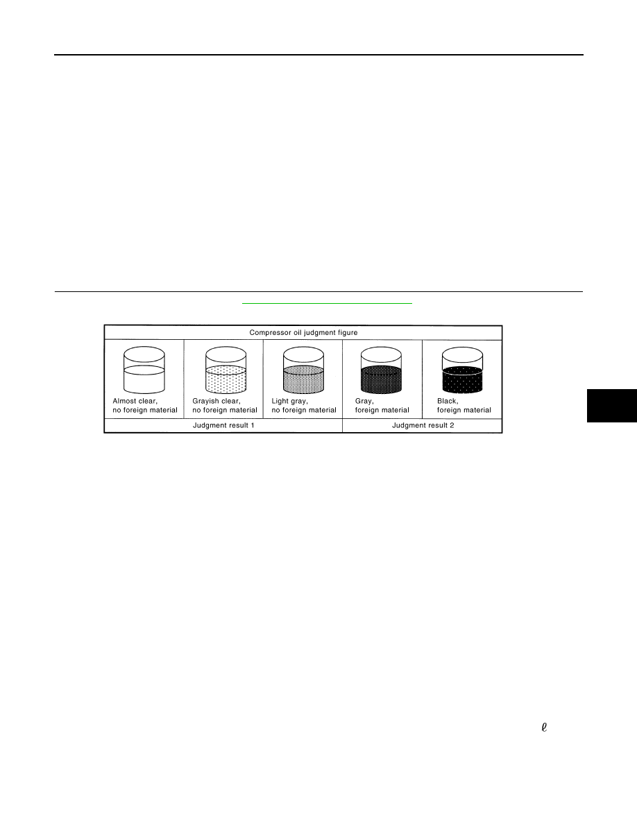
COMPRESSOR OIL JUDGMENT
1.
Remove the compressor. Refer to
HA-121, "Removal and Installation"
2.
Sample a compressor oil and judge on the figure.
Judgement result 1>>Replace compressor only.
Judgement result 2>>Replace compressor and condenser & liquid tank assembly.
Perform Lubricant Return Operation
INFOID:0000000010704944
CAUTION:
If a large amount of refrigerant or lubricant leakage is detected, never perform lubricant return opera-
tion.
1.
Start the engine and set to the following conditions.
• Engine speed: Idling to 1,200 rpm
• A/C switch: ON
• Fan (blower) speed: Maximum speed set
• Intake door position: Recirculation
• Temperature setting: Full cold
2.
Perform lubricant return operation for approximately 10 minutes.
3.
Stop the engine.
4.
Lubricant return operation is complete.
Lubricant Adjusting Procedure for Components Replacement Except Compressor
INFOID:0000000010704945
Fill with lubricant for the amount that is calculated according to the following conditions.
Example: Lubricant amount to be added when replacing evaporator and condenser & liquid tank [m (Imp fl
oz)] = 45 (1.6) + 15 (0.5) +
α
Name
: ND-OIL8
JSIIA0927GB