Qashqai J11. Heater & Air conditioning System - part 6
CONDENSER
HA-81
< REMOVAL AND INSTALLATION >
[TYPE 2]
C
D
E
F
G
H
J
K
L
M
A
B
HA
N
O
P
CONDENSER
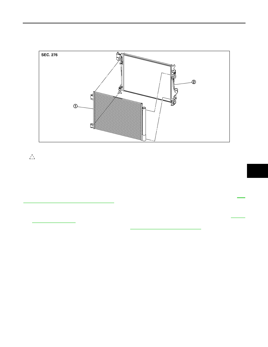
Exploded View
INFOID:0000000010501542
CONDENSER
CONDENSER : Removal and Installation
INFOID:0000000010501543
CAUTION:
Perform lubricant return operation before each refrigeration system disassembly. However, if a large
amount of refrigerant or lubricant is detected, never perform lubricant return operation. Refer to
66, "Perform Lubricant Return Operation"
REMOVAL
1.
Use a refrigerant collecting equipment (for HFO-1234yf) to discharge the refrigerant. Refer to
2.
Remove front bumper fascia assembly. Refer to
EXT-19, "Removal and Installation"
.
3.
Remove mounting bolt, and then disconnect high-pressure pipe 1 from the condenser & liquid tank
assembly.
CAUTION:
Cap or wrap the joint of the A/C piping and condenser with suitable material such as vinyl tape to
avoid the entry of air.
4.
Remove mounting bolt, and then disconnect high-pressure pipe 2 from the condenser & liquid tank
assembly.
CAUTION:
Cap or wrap the joint of the A/C piping and condenser with suitable material such as vinyl tape to
avoid the entry of air.
5.
Disengage fixing pawls, and then remove the condenser & liquid tank assembly from the vehicle.
CAUTION:
Never to damage core surface of condenser.
INSTALLATION
Note the following items, and then install in the reverse order of removal.
CAUTION:
• Replace O-rings with new ones. Then apply compressor oil to them when installing.
1.
Condenser &liquid tank assembly
2.
Radiator
: Pawl
JMIIA3533ZZ