Qashqai J11. Engine lubrication system (HRA2DDT, K9K, MR20DD) - part 2
 

  Index      Nissan     Qashqai J11. Engine lubrication system (HRA2DDT, K9K, MR20DD). Service and Repair Manual


Search            copyright infringement  


Content      ..      1      2      3      ..


Qashqai J11. Engine lubrication system (HRA2DDT, K9K, MR20DD) - part 2


PRECAUTIONS

LU-17

< PRECAUTION >

[MR20DD]

C

D

E

F

G

H

I

J

K

L

M

A

LU

N

P

O

• After disassembling, or exposing any internal engine parts, change engine oil and replace oil filter with a new

one.

• Release air within route when refilling after draining engine coolant. 
• After repairing, start the engine and increase engine speed to check engine coolant, fuel, engine oil, and

exhaust gases for leakage.

Liquid Gasket

INFOID:0000000010624149

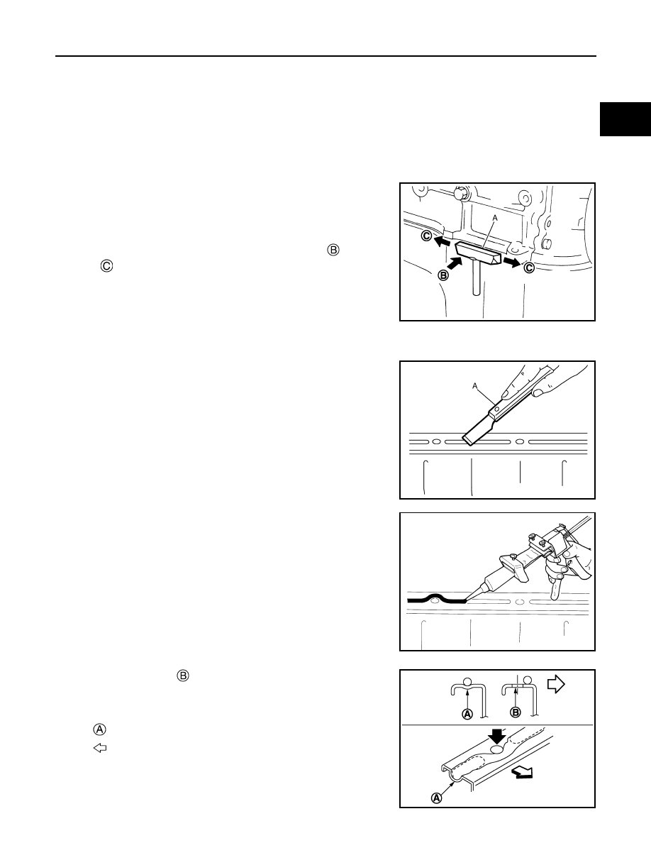
REMOVAL OF LIQUID GASKET SEALING

• After removing mounting nuts and bolts, separate the mating sur-

face using the seal cutter [SST: KV10111100] (A) and remove old
liquid gasket sealing.

CAUTION:

Never damage the mating surfaces.

• Tap the seal cutter [SST: KV10111100] to insert it 

, and then

slide it 

 by tapping on the side as shown in the figure.

• In areas where the seal cutter [SST: KV10111100] is difficult to use,

lightly tap the parts using a plastic hammer to remove it.

CAUTION:

If for some unavoidable reason tool such as a screwdriver is
used, be careful not to damage the mating surfaces.

LIQUID GASKET APPLICATION PROCEDURE

1.

Using a scraper (A), remove old liquid gasket adhering to the liq-
uid gasket application surface and the mating surface.
• Remove liquid gasket completely from the groove of the liquid

gasket application surface, mounting bolts, and bolt holes.

2.

Wipe the liquid gasket application surface and the mating sur-
face with white gasoline (lighting and heating use) to remove
adhering moisture, grease and foreign materials.

3.

Attach liquid gasket tube to the tube presser (commercial ser-
vice tool).
Use Genuine Liquid Gasket or equivalent.

4.

Apply liquid gasket without gaps to the specified location accord-
ing to the specified dimensions.
• If there is a groove for liquid gasket application, apply liquid

gasket to the groove.

• As for bolt holes 

, normally apply liquid gasket inside the

holes. Occasionally, it should be applied outside the holes.
Check to read the text of this manual.

• Within five minutes of liquid gasket application, install the mat-

ing component.

• If liquid gasket protrudes, wipe it off immediately.
• Do not retighten mounting bolts or nuts after the installation.

JPBIA0052ZZ

JPBIA0053ZZ

EMA0622D

: Groove

: Inside

JPBIA0010ZZ

LU-18

< PRECAUTION >

[MR20DD]

PRECAUTIONS

• After 30 minutes or more have passed from the installation, fill engine oil and engine coolant.

CAUTION:

If there are specific instructions in this manual, observe them.

PREPARATION

LU-19

< PREPARATION >

[MR20DD]

C

D

E

F

G

H

I

J

K

L

M

A

LU

N

P

O

PREPARATION

PREPARATION

Special Service Tools

INFOID:0000000010624150

Commercial Service Tools

INFOID:0000000010624151

Tool number
Tool name

Description

ST25051001
Oil pressure gauge

Measuring oil pressure
Maximum measuring range: 2,452 kPa 

(24.52 bar, 25 kg/cm

2

, 356 psi)

ST25052000
Hose

Adapting oil pressure gauge to cylinder block

KV10115801
Oil filter wrench

Removing and installing oil filter
a: 64.3 mm (2.531 in)

NT050

S-NT559

S-NT375

Tool name

Description

Deep socket

Removing and installing oil pressure switch 
27 mm (1.06 in)

PBIC4066E

LU-20

< SYSTEM DESCRIPTION >

[MR20DD]

DESCRIPTION

SYSTEM DESCRIPTION

DESCRIPTION

Engine Lubrication System

INFOID:0000000010624152

Camshaft (EXH)

Intake valve timing controller

Exhaust valve timing controller

Exhaust valve timing control sole-
noid valve

Intake valve timing control solenoid 
valve

Timing chain tensioner

Timing chain oil jet

Timing chain

Oil pump drive chain

Oil pan

Oil pump

Oil strainer

Balancer unit

Oil cooler

Oil filter

Crankshaft

Piston oil jet

Camshaft (INT)

High pressure fuel pump

Main gallery

JPBIA6905ZZ

DESCRIPTION

LU-21

< SYSTEM DESCRIPTION >

[MR20DD]

C

D

E

F

G

H

I

J

K

L

M

A

LU

N

P

O

Engine Lubrication System Schematic

INFOID:0000000010624153

JPBIA6906GB

LU-22

< PERIODIC MAINTENANCE >

[MR20DD]

ENGINE OIL

PERIODIC MAINTENANCE

ENGINE OIL

Inspection

INFOID:0000000010624154

ENGINE OIL LEVEL

NOTE:
Before starting engine, put vehicle horizontally and check the engine oil level. If engine is already started, stop
it and allow 10 minutes before checking.

1.

Pull out oil level gauge and wipe it clean.

2.

Insert oil level gauge and check that the engine oil level is within
the range 

 shown in the figure.

3.

If it is out of range, adjust it.

ENGINE OIL APPEARANCE

• Check engine oil for white turbidity or heavy contamination.
• If engine oil becomes turbid and white, it is highly probable that it is contaminated with engine coolant.

Repair or replace damaged parts.

ENGINE OIL LEAKAGE 

Check for engine oil leakage around the following area.
• Oil pan (upper and lower)
• Oil pan drain plug
• Oil pressure sensor
• Oil filter
• Oil cooler
• Intake valve timing control solenoid valve
• Exhaust valve timing control solenoid valve
• Front cover
• VTC cover
• Mating surface between cylinder block and cylinder head
• Mating surface between cylinder head and camshaft bracket
• Mating surface between camshaft bracket and rocker cover
• Mating surface between camshaft bracket and high pressure fuel pump
• Crankshaft oil seals (front and rear)

OIL PRESSURE CHECK

WARNING:

• Be careful not to get burned, as engine oil may be hot.
• When checking engine oil pressure, shift position should be “Parking position”, and apply parking

brake securely.

1.

Check engine oil level.

PBIC3309J

ENGINE OIL

LU-23

< PERIODIC MAINTENANCE >

[MR20DD]

C

D

E

F

G

H

I

J

K

L

M

A

LU

N

P

O

2.

Disconnect harness connector at oil pressure sensor 

, and

remove oil pressure sensor using a deep socket (commercial
service tool).

CAUTION:

Never drop or shock oil pressure switch.

3.

Install oil pressure gauge [SST: ST25051001] (A) and hose
[SST: ST25052000] (B).

4.

Start engine and warm it up to normal operating temperature.

5.

Check oil pressure with engine running under no-load.
NOTE:
When engine oil temperature is low, engine oil pressure becomes high.

If difference is extreme, check oil passage and oil pump for oil leakage.

6.

After the inspections, install oil pressure switch as follows:

a.

Remove old liquid gasket adhering to oil pressure switch and engine.

b.

Apply liquid gasket and tighten oil pressure switch to specification.
Use Genuine Liquid Gasket or equivalent.

c.

Check engine oil level.

d.

After warming up engine, check that there is no leakage of engine oil with running engine.

Draining

INFOID:0000000010624155

WARNING:

• Be careful not to get burned, as engine oil may be hot.
• Prolonged and repeated contact with used engine oil may cause skin cancer. Try to avoid direct skin

contact with used engine oil. If skin contact is made, wash thoroughly with soap or hand cleaner as
soon as possible. 

1.

Warm up the engine, and check for engine oil leakage from engine components. Refer to 

LU-22, "Inspec-

tion"

.

2.

Stop the engine and wait for 10 minutes.

3.

Loosen oil filler cap.

4.

Remove drain plug and then drain engine oil.

Refilling

INFOID:0000000010624156

1.

Install drain plug with new drain plug washer. Refer to 

EM-156, "Exploded View"

.

: Oil pan (lower)

: Engine front

JSBIA4317ZZ

JPBIA0074ZZ

Engine oil pressure

Refer to 

LU-30, "Engine Oil Pressure"

.

Tightening torque

: Refer to 

EM-222, "Exploded View"

.

LU-24

< PERIODIC MAINTENANCE >

[MR20DD]

ENGINE OIL

CAUTION:

• Do not reuse drain plug washer.
• Be sure to clean drain plug and install with new drain plug washer.

2.

Refill with new engine oil.
Engine oil specification and viscosity: Refer to 

MA-59, "Fluids and Lubricants"

.

CAUTION:

• The refill capacity depends on the engine oil temperature and drain time. Use these specifica-

tions for reference only.

• Always use oil level gauge to determine the proper amount of engine oil in the engine.

3.

Warm up engine and check area around drain plug and oil filter for engine oil leakage.

4.

Stop engine and wait for 10 minutes.

5.

Check the engine oil level. Refer to 

LU-22, "Inspection"

.

Tightening torque

: Refer to 

EM-156, "Exploded View"

.

Engine oil capacity

Refer to 

LU-30, "Periodical Maintenance Specification"

.

OIL FILTER

LU-25

< PERIODIC MAINTENANCE >

[MR20DD]

C

D

E

F

G

H

I

J

K

L

M

A

LU

N

P

O

OIL FILTER

Removal and Installation

INFOID:0000000010624157

REMOVAL

• Using oil filter wrench [SST: KV10115801](A), remove oil filter 

.

CAUTION:

• Oil filter is provided with relief valve. Use Genuine NISSAN

Oil Filter or equivalent.

• Be careful not to get burned when engine and engine oil

may be hot.

• When removing, prepare a shop cloth to absorb any engine

oil leakage or spillage.

• Completely wipe off any engine oil that adheres to engine

and vehicle.

INSTALLATION

1.

Remove foreign materials adhering to the oil filter installation surface.

2.

Apply new engine oil to the oil seal contact surface of new oil fil-
ter.

3.

Screw oil filter manually until it touches the installation surface,
then tighten it by 2/3 turn 

. Or tighten to specification.

Inspection

INFOID:0000000010624158

INSPECTION AFTER INSTALLATION

1.

Check the engine oil level. Refer to 

LU-22, "Inspection"

.

2.

Start the engine, and check there is no leakage of engine oil.

3.

Stop the engine and wait for 10 minutes.

4.

Check the engine oil level, and adjust the level. Refer to 

LU-22, "Inspection"

.

: Engine front

JSBIA4402ZZ

SMA010

Oil filter:

: 17.7 N·m (1.8 kg-m, 13 ft-lb)

JPBIA0077ZZ

LU-26

< REMOVAL AND INSTALLATION >

[MR20DD]

OIL COOLER

REMOVAL AND INSTALLATION

OIL COOLER

Exploded View

INFOID:0000000010624159

M/T models

JPBIA6894GB

Clamp

Water hose

Oil filter

Connector bolt

Oil cooler

Water hose

To thermostat housing

To thermostat housing

Comply with the assembly procedure 
when tightening. Refer to 

LU-25

: Always replace after every disassembly.

: N·m (kg-m, ft-lb)

OIL COOLER

LU-27

< REMOVAL AND INSTALLATION >

[MR20DD]

C

D

E

F

G

H

I

J

K

L

M

A

LU

N

P

O

CVT models

Removal and Installation

INFOID:0000000010624160

REMOVAL

WARNING:

Be careful not to get burn yourself, as engine oil and engine coolant may be hot.

1.

Drain engine coolant from radiator and cylinder block. Refer to 

CO-38, "Draining"

.

NOTE:
Perform this step when removing water hoses.

2.

Using oil filter wrench [SST: KV10115801], remove oil filter. Refer to 

LU-25, "Removal and Installation"

.

3.

Disconnect water hoses from oil cooler.
• When removing oil cooler only, pinching water hoses near oil cooler to prevent engine coolant from spill-

ing out.

• Remaining engine coolant in piping will come out. Use a tray to collect it.

CAUTION:

Perform this step when the engine is cold.

4.

Remove connector bolt, and remove oil cooler.

INSTALLATION

Installation is the reverse order of removal.

JPBIA6895GB

Clamp

Water hose

Oil filter

Connector bolt

Oil cooler

Water hose

Heater thermostat

Water hose

To thermostat housing

To thermostat housing

Comply with the assembly procedure 
when tightening. Refer to 

LU-25

: Always replace after every disassembly.

: N·m (kg-m, ft-lb)

LU-28

< REMOVAL AND INSTALLATION >

[MR20DD]

OIL COOLER

• Tighten the connector bolt 

 after aligning the stopper 

 on the oil

pan (upper) side with protrusion of oil cooler 

.

Inspection

INFOID:0000000010624161

INSPECTION AFTER REMOVAL

Oil Cooler

Check oil cooler for cracks. Check oil cooler for clogging by blowing through engine coolant inlet. If necessary,
replace oil cooler.

INSPECTION AFTER INSTALLATION

1.

Check the engine oil level and the engine coolant level and add engine oil and engine coolant. Refer to

LU-22, "Inspection"

 and 

CO-38, "Inspection"

.

2.

Start the engine, and check that there is no leakage of engine oil or engine coolant.

3.

Stop the engine and wait for 10 minutes.

4.

Check the engine oil level and the engine coolant level again. Refer to 

LU-22, "Inspection"

 and 

CO-38,

"Inspection"

.

: Engine front

JPBIA6907ZZ

OIL PUMP

LU-29

< UNIT DISASSEMBLY AND ASSEMBLY >

[MR20DD]

C

D

E

F

G

H

I

J

K

L

M

A

LU

N

P

O

UNIT DISASSEMBLY AND ASSEMBLY

OIL PUMP

Exploded View

INFOID:0000000010624162

Oil pump is integrated in the oil pan (upper). Refer to 

EM-218, "Exploded View"

.

LU-30

< SERVICE DATA AND SPECIFICATIONS (SDS) 

[MR20DD]

SERVICE DATA AND SPECIFICATIONS (SDS)

SERVICE DATA AND SPECIFICATIONS (SDS)

SERVICE DATA AND SPECIFICATIONS (SDS)

Periodical Maintenance Specification

INFOID:0000000010624163

ENGINE OIL CAPACITY (APPROXIMATE)

Unit: 

 (lmp qt)

Engine Oil Pressure

INFOID:0000000010624164

Unit: kPa (bar, kg/cm

2

, psi)

*: Engine oil temperature at 80

°

C (176

°

F)

Drain and refill 

With oil filter change

3.8 (3-3/8)

Without oil filter change

3.6 (3-1/8)

Dry engine (Overhaul)

4.4 (3-7/8)

Engine speed

Approximate discharge pressure*

Idle speed

More than 85 (0.85, 0.867, 12.3)

2,000 rpm

More than 200 (2.0, 2.04, 29) 

PRECAUTIONS

LU-31

< PRECAUTION >

[K9K]

C

D

E

F

G

H

I

J

K

L

M

A

LU

N

P

O

PRECAUTION

PRECAUTIONS

Precaution for Liquid Gasket

INFOID:0000000010284204

REMOVAL OF LIQUID GASKET

• After removing the mounting bolts and nuts, separate the mating

surface using a seal cutter and remove the liquid gasket.

CAUTION:

Be careful not to damage the mating surfaces.

• In areas where the cutter is difficult to use, use a plastic hammer to

lightly tap the gasket applied area.

CAUTION:

If for some unavoidable reason a tool such as a flat-bladed
screwdriver is used, be careful not to damage the mating sur-
faces.

LIQUID GASKET APPLICATION PROCEDURE 

1.

Using a scraper, remove the old liquid gasket adhering to the
gasket application surface and the mating surface.
• Remove the liquid gasket completely from the groove of the

gasket application surface, mounting bolts and bolt holes.

2.

Wipe the gasket application surface and the mating surface with
white gasoline (lighting and heating use) to remove adhering
moisture, grease and foreign materials.

3.

Attach the liquid gasket to the tube presser.
Use Genuine Liquid Gasket or equivalent.

4.

Apply the gasket without breaks to the specified location with the
specified dimensions.
• If there is a groove for the liquid gasket application, apply the

gasket to the groove.

• As for the bolt holes, normally apply the gasket inside the

holes. If specified, it should be applied outside the holes. Make
sure to read the instruction in this manual.

• Within five minutes of gasket application, install the mating

component.

• If the liquid gasket protrudes, wipe it off immediately.
• Do not retighten after the installation.
• After 30 minutes or more have passed from the installation, fill

the engine oil and coolant.

CAUTION:

If there are instructions in this manual, observe them.

PBIC0275E

PBIC0003E

EMA0622D

SEM159F

LU-32

< PRECAUTION >

[K9K]

PRECAUTIONS

Precautions for Removing Battery Terminal

INFOID:0000000010508724

• With the adoption of Auto ACC function, ACC power is automatically supplied by operating the intelligent key

or remote keyless entry or by opening/closing the driver side door. In addition, ACC power is supplied even
after the ignition switch is turned to the OFF position, i.e. ACC power is supplied for a certain fixed time.

• When disconnecting the 12V battery terminal, turn off the ACC

power before disconnecting the 12V battery terminal, observing
“How to disconnect 12V battery terminal” described below.
NOTE:
Some ECUs operate for a certain fixed time even after ignition
switch is turned OFF and ignition power supply is stopped. If the
battery terminal is disconnected before ECU stops, accidental DTC
detection or ECU data damage may occur.

•  For vehicles with the 2-batteries, be sure to connect the main bat-

tery and the sub battery before turning ON the ignition switch.
NOTE:
If the ignition switch is turned ON with any one of the terminals of
main battery and sub battery disconnected, then DTC may be detected.

•  After installing the 12V battery, always check "Self Diagnosis Result" of all ECUs and erase DTC.

NOTE:
The removal of 12V battery may cause a DTC detection error.

HOW TO DISCONNECT 12V BATTERY TERMINAL

Disconnect 12V battery terminal according to Instruction 1 or Instruction 2 described below.
For vehicles parked by ignition switch OFF, refer to Instruction 2.

INSTRUCTION 1

1.

Open the hood.

2.

Turn key switch to the OFF position with the driver side door opened.

3.

Get out of the vehicle and close the driver side door.

4.

Wait at least 3 minutes. For vehicle with the engine listed below, remove the battery terminal after a lapse
of the specified time.

CAUTION:

While waiting, never operate the vehicle such as locking, opening, and closing doors. Violation of
this caution results in the activation of ACC power supply according to the Auto ACC function.

5.

Remove 12V battery terminal.

CAUTION:

After installing 12V battery, always check self-diagnosis results of all ECUs and erase DTC.

INSTRUCTION 2 (FOR VEHICLES PARKED BY IGNITION SWITCH OFF)

1.

Unlock the door with intelligent key or remote keyless entry.
NOTE:
At this moment, ACC power is supplied.

2.

Open the driver side door.

3.

Open the hood.

4.

Close the driver side door.

5.

Wait at least 3 minutes.

CAUTION:

While waiting, never operate the vehicle such as locking, opening, and closing doors. Violation of
this caution results in the activation of ACC power supply according to the Auto ACC function.

6.

Remove 12V battery terminal.

SEF289H

D4D engine

: 20 minutes

HRA2DDT

: 12 minutes

K9K engine

: 4 minutes

M9R engine

: 4 minutes

R9M engine

: 4 minutes

V9X engine

: 4 minutes


Content      ..      1      2      3      ..