Qashqai J11. Engine mechanical (HRA2DDT, K9K, MR20DD) - part 23


  Index      Nissan     Qashqai J11. Engine mechanical (HRA2DDT, K9K, MR20DD). Service and Repair Manual


Search            copyright infringement  


Content      ..     21      22      23      24     ..


Qashqai J11. Engine mechanical (HRA2DDT, K9K, MR20DD) - part 23


SERVICE DATA AND SPECIFICATIONS (SDS)

EM-353

< SERVICE DATA AND SPECIFICATIONS (SDS) 

[K9K]

C

D

E

F

G

H

I

J

K

L

M

A

EM

N

P

O

VALVE LIFTER

Unit: mm (in)

VALVE CLEARANCE

Unit: mm (in)

AVAILABLE VALVE LIFTER

Unit: mm (in)

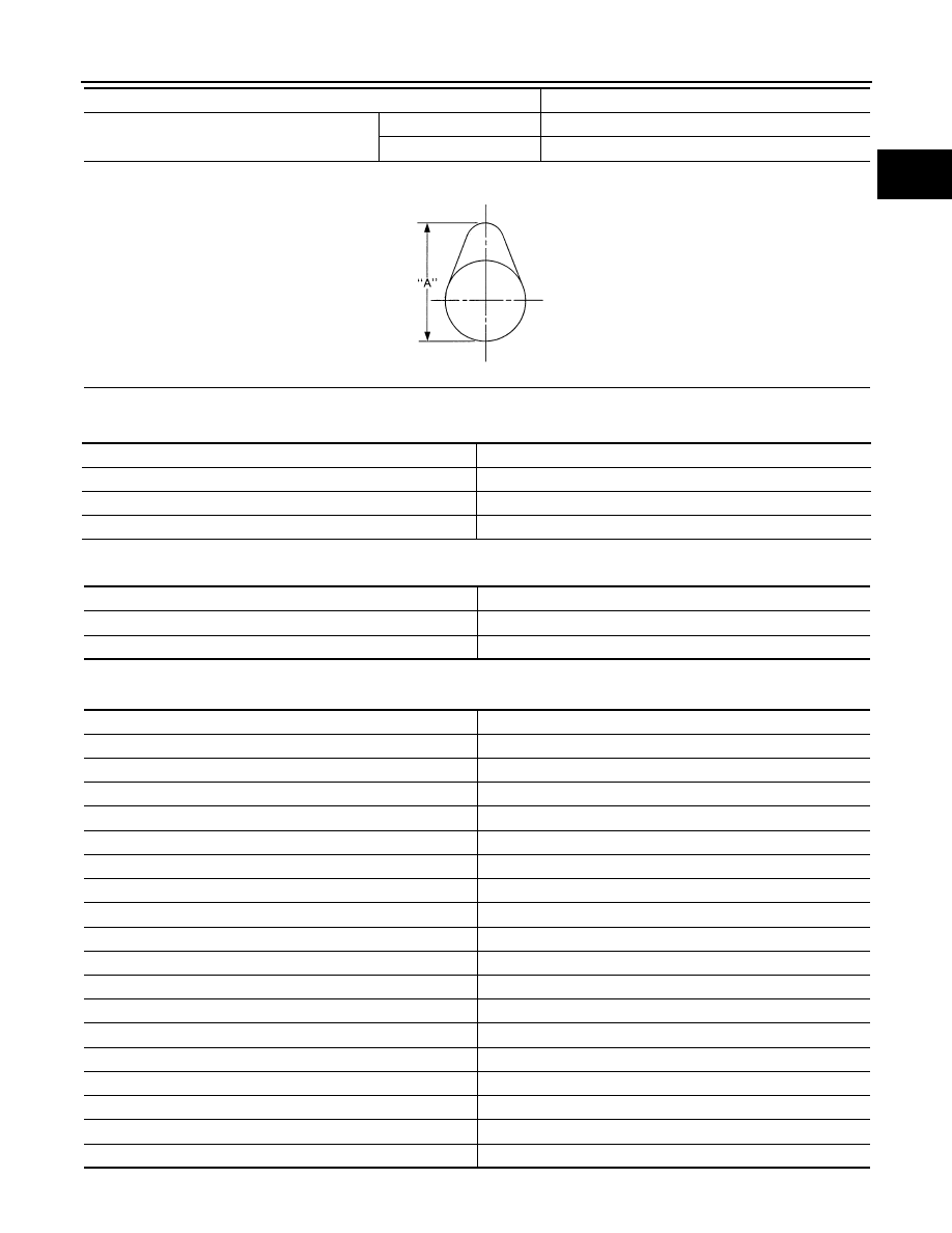
Camshaft cam height “A”

Intake

44.012 - 44.018 (1.7327 - 1.7329)

Exhaust

44.592 - 44.598 (1.7555 - 1.7557)

Items

Standard

SEM671

Items

Standard

Valve lifter outer diameter

34.965 - 34.985 (1.3767 - 1.3774)

Valve lifter hole diameter

35.000 - 35.040 (1.3780 - 1.3795)

Valve lifter clearance

0.015 - 0.075 (0.0006 - 0.0030)

Items

Cold

Intake

0.125 - 0.250 (0.0049 - 0.0098)

Exhaust

0.325 - 0.450 (0.0128 - 0.0177)

Part number

Thickness

13229BN700

7.550 (0.2972)

13229BN701

7.575 (0.2982)

13229BN702

7.600 (0.2992)

13229BN703

7.625 (0.3002)

13229BN704

7.650 (0.3012)

13229BN705

7.675 (0.3022)

13229BN706

7.700 (0.3031)

13229BN707

7.725 (0.3041)

13229BN708

7.750 (0.3051)

13229BN709

7.775 (0.3061)

13229BN710

7.800 (0.3071)

13229BN711

7.825 (0.3081)

13229BN712

7.850 (0.3091)

13229BN713

7.875 (0.3100)

13229BN714

7.900 (0.3110)

13229BN715

7.925 (0.3120)

13229BN716

7.950 (0.3130)

13229BN717

7.975 (0.3140)

EM-354

< SERVICE DATA AND SPECIFICATIONS (SDS) 

[K9K]

SERVICE DATA AND SPECIFICATIONS (SDS)

Cylinder Head

INFOID:0000000010282110

CYLINDER HEAD

Unit: mm (in)

VALVE DIMENSIONS

13229BN718

8.000 (0.3150)

13229BN719

8.025 (0.3159)

13229BN720

8.050 (0.3169)

13229BN721

8.075 (0.3179)

13229BN722

8.100 (0.3189)

13229BN723

8.125 (0.3199)

13229BN724

8.150 (0.3209)

Part number

Thickness

Items

Standard

Cylinder head gasket thickness

0.68 - 0.74 (0.0269 - 0.0291)

Head surface distortion

Less than 0.05 (0.002)

Normal cylinder head height “H”

127 (5.000)

E1BIA0063ZZ

Items

Standard

Valve head diameter “D”

mm (in)

Intake

33.38 - 33.62 (1.314 - 1.324)

Exhaust

28.88 - 29.12 (1.137 - 1.146)

Valve length “L”

mm (in)

Intake

100.74 - 101.16 (3.9661 - 3.9827)

Exhaust

100.54 - 100.96 (3.9583 - 3.9748)

Valve stem diameter “d”

mm (in)

Intake

5.969 - 5.985 (0.2350 - 0.2356)

Measuring point (X1) is 41 (1.61)

Exhaust

5.955 - 5.971 (0.2344 - 0.2351)

Measuring point (X1) is 31 (1.22)

Valve seat angle “

α

degree

45

°

00

 (45.00

°

)

Valve margin “T”

mm (in)

1.0 (0.039)

SERVICE DATA AND SPECIFICATIONS (SDS)

EM-355

< SERVICE DATA AND SPECIFICATIONS (SDS) 

[K9K]

C

D

E

F

G

H

I

J

K

L

M

A

EM

N

P

O

VALVE GUIDE

VALVE SEAT

Valve lift

mm (in)

Intake

8.0 (0.315)

Exhaust

8.6 (0.339)

Items

Standard

E1BIA0064ZZ

Items

Standard

Valve guide

mm (in)

Length

40.35 - 40.65 (1.5886 - 1.6004)

Outer diameter

10.956 - 11.062 (0.4313 - 0.4355)

Inner diameter (Finished 
size)

6.000 - 6.018 (0.2362 - 0.2369)

Cylinder head valve guide hole diameter

mm (in)

11.0 (0.4431)

Valve guide clearance

mm (in)

Intake

0.020 - 0.050 (0.0008 - 0.0020)

Exhaust

0.030 - 0.063 (0.0012 - 0.0025)

Projection length “A”

mm (in)

Intake

14.0 (0.5512)

Exhaust

14.2 (0.5591)

Valve guide inclination angle “a”

degree

90

°

00

 (90.00

°

)

E1BIA0065ZZ

Items

Standard

Cylinder head seat recess diameter “D”

mm (in)

Intake

34.444 - 34.474 (1.3561 - 1.3572)

Exhaust

29.955 - 29.985 (1.1793 - 1.1805)

Valve seat outer diameter “D”

mm (in)

Intake

34.534 - 34.550 (1.3596 - 1.3602)

Exhaust

30.035 - 30.048 (1.1825 - 1.1830)

Angle “

α

degree

89

°

30

 (89.50

°

)

Contacting width “X”

mm (in)

1.8 (0.071)

Valve seat height “H”

mm (in)

Intake

4.61 - 4.69 (0.1815 - 0.1846)

Exhaust

5.63 - 5.71 (0.2217 - 0.2248)

EM-356

< SERVICE DATA AND SPECIFICATIONS (SDS) 

[K9K]

SERVICE DATA AND SPECIFICATIONS (SDS)

VALVE SPRING

Cylinder Block

INFOID:0000000010282111

CYLINDER BLOCK

Unit: mm (in)

PISTON MARKING

Cylinder head seat recess depth “H”

mm (in)

Intake

6.0 (0.236)

Exhaust

7.0 (0.276)

Items

Standard

E1BIA0066ZZ

Items

Standard

Free height

mm (in)

43.31 (1.7051)

Pressure                                N (kg, lb) at height mm (in)

218 - 242 (22.2 - 24.7, 49.0 - 54.4) at 33.80 (1.3307)

477 - 523 (48.7 - 53.3, 107.2 - 117.6) at 24.80 (0.9764)

Spring squareness

mm (in)

1.2 (0.047)

Full pressed height

mm (in)

23.40 (0.9213)

Diameter of wire

mm (in)

3.45 (0.1358)

Outer diameter at the top of spring

mm (in)

20.8 - 21.2 (0.8189 - 0.8346)

Outer diameter at the bottom of spring

mm (in)

25.5 - 25.9 (1.0039 - 1.0197)

Inner diameter at the top of spring

mm (in)

13.9 - 14.3 (0.5472 - 0.5630)

Inner diameter at the bottom of spring

mm (in)

18.6 - 19.0 (0.7323 - 0.7480)

Items

Standard

Cylinder block top surface clearance

Less than 0.05 (0.002)

1

Direction of fitting of the piston mark towards the flywheel

2

Height between the piston pin and the top of the piston (see table below).

MBIB0337E

SERVICE DATA AND SPECIFICATIONS (SDS)

EM-357

< SERVICE DATA AND SPECIFICATIONS (SDS) 

[K9K]

C

D

E

F

G

H

I

J

K

L

M

A

EM

N

P

O

PISTON

Unit: mm (in)

PISTON RING

Unit: mm (in)

PISTON PIN

Unit: mm (in)

3

Used by the supplier only

4

Used by the supplier only

5

Used by the supplier only

6

Piston axis of symmetry

7

Piston pin hole axis

8

Offset between the hole axis (7) and the piston's axis of symmetry (6) is 0.3 mm (0.012 in)

Items

Standard

Piston skirt diameter “A”

mm (in)

75.938 - 75.952 (2.9897 - 2.9902)

“a” dimension

mm (in)

56.0 (2.205)

Piston pin hole diameter

mm (in)

Category J

41.605 - 41.646 (1.6380 - 1.6396)

Category K

41.647 - 41.688 (1.6396 - 1.6413)

Category L

41.689 - 41.730 (1.6413 - 1.6429)

Category M

41.731 - 41.772 (1.6429 - 1.6446)

Category N

41.773 - 41.814 (1.6446 - 1.6462)

Capacity of combustion chamber

m

 (Imp fl oz)

19.89 - 20.39 (0.78 - 0.80)

Piston protrusion

mm (in)

0.023 - 0.281 (0.009 - 0.011)

SEM882E

Items

Standard

Thickness

Top

1.97 - 1.99 (0.0776 - 0.0783)

2nd

1.97 - 1.99 (0.0776 - 0.0783)

Oil ring

2.47 - 2.49 (0.0972 - 0.0980)

Side clearance

Top

0.10 - 0.12 (0.0039 - 0.0047)

2nd

0.08 - 0.10 (0.0031 - 0.0039)

Oil ring

0.03 - 0.07 (0.0011 - 0.0027)

Piston ring end gap

Top

0.20 - 0.35 (0.0079 - 0.0138)

2nd

0.70 - 0.90 (0.0276 - 0.0354)

Oil ring

0.25 - 0.50 (0.0098 - 0.0197)

Items

Standard

Length

57.97 - 60.0 (2.282 - 2.362)

Piston pin outer diameter

25.995 - 26.000 (1.0234 - 1.0236)

EM-358

< SERVICE DATA AND SPECIFICATIONS (SDS) 

[K9K]

SERVICE DATA AND SPECIFICATIONS (SDS)

CONNECTING ROD

Unit: mm (in)

CRANKSHAFT

Unit: mm (in)

Turbocharger

INFOID:0000000010282112

Items

Standard

Center distance

133.75 (5.266)

Connecting rod small end diameter (with bush)

26.013 - 26.025 (1.0241 - 1.0246)

Connecting rod big end diameter

47.610 - 47.627 (1.8744 - 1.8751)

Big end longitudinal play

0.205 - 0.467 (0.0081 - 0.0184)

Big end radial play

0.016 - 0.07 (0.0006 - 0.0027)

Items

Standard

Main journal diameter “Dm”

47.99 - 48.01 (1.8894 - 1.8902)

Pin journal diameter “Dp”

43.96 - 43.98 (1.7307 - 1.7315)

Maximum run-out allowed on the flywheel bearing face of the flywheel

0.6 (0.024)

Lateral play (without lateral shim)

0.045 - 0.252 (0.0018 - 0.0099)

Lateral play (with lateral shim)

0.045 - 0.852 (0.0018 - 0.0335)

Journal radial play

0.010 - 0.054 (0.0004 - 0.0021)

E1BIA0067ZZ

Items

Standard

Regulation value operating vacuum

kPa (bar, kg/cm

2

, psi)

40 (0.4, 0.4, 5.8)

Valve rod moving length

mm (in)

1.4 (0.055)

NOISE, VIBRATION AND HARSHNESS (NVH) TROUBLESHOOTING

EM-359

< SYMPTOM DIAGNOSIS >

[R9M]

C

D

E

F

G

H

I

J

K

L

M

A

EM

N

P

O

SYMPTOM DIAGNOSIS

NOISE, VIBRATION AND HARSHNESS (NVH) TROUBLESHOOTING

NVH Troubleshooting - Engine Noise

INFOID:0000000010281953

JPBIA0854GB

EM-360

< SYMPTOM DIAGNOSIS >

[R9M]

NOISE, VIBRATION AND HARSHNESS (NVH) TROUBLESHOOTING

Use the Chart Below to Help You Find the Cause of the Symptom

INFOID:0000000010281954

1.

Locate the area where noise occurs.

2.

Confirm the type of noise.

3.

Specify the operating condition of engine.

4.

Check specified noise source.

If necessary, repair or replace these parts.

A: Closely related

B: Related

C: Sometimes related

—: Not related

Location 

of noise

Type of 

noise

Operating condition of engine

Source of 

noise

Check item

Refer-

ence page

Before 

warm-

up

After 

warm-

up

When 

start-

ing

When 

idling

When 

racing

While 

driving

Top of en-
gine
Cylinder 
head

Ticking or 
clicking

A

C

B

B

Hydraulic 
tappet 
noise

Out of oil 

EM-404

Rattle

C

A

A

B

C

Camshaft 
bearing 
noise

Camshaft journal oil 
clearance

EM-421

Crank-
shaft pul-
ley
Cylinder 
block 
(Side of 
engine)
Oil pan

Slap or 
knock

A

B

B

Piston pin 
noise

Piston to piston pin oil 
clearance
Connecting rod bushing 
oil clearance

EM-459

Slap or 
rap

A

B

B

A

Piston 
slap noise

Piston ring side clear-
ance
Piston ring end gap

EM-459

Knock

A

B

C

B

B

B

Connect-
ing rod 
bearing 
noise

Connecting rod bushing 
oil clearance 
Connecting rod bearing 
oil clearance

EM-459

Knock

A

B

A

B

C

Main bear-
ing noise

Main bearing oil clear-
ance

EM-459

Front of 
engine
Front cov-
er

Tapping or 
ticking

A

A

B

B

B

Timing 
chain and 
chain ten-
sioner 
noise

Timing chain cracks 
and wear
Timing chain tensioner 
operation

EM-418

Front of 
engine

Squeak-
ing or fizz-
ing

A

B

B

C

Drive belt 
(Sticking 
or slip-
ping)

Drive belt deflection

EM-378

Creaking

A

B

A

B

A

B

Drive belt 
(Slipping)

Idler pulley bearing op-
eration

Squall
Creak

A

B

B

A

B

Water 
pump 
noise

Water pump operation

CO-100, 

"Exploded 

View"

PRECAUTIONS

EM-361

< PRECAUTION >

[R9M]

C

D

E

F

G

H

I

J

K

L

M

A

EM

N

P

O

PRECAUTION

PRECAUTIONS

Precaution for Supplemental Restraint System (SRS) "AIR BAG" and "SEAT BELT 
PRE-TENSIONER"

INFOID:0000000010499455

The Supplemental Restraint System such as “AIR BAG” and “SEAT BELT PRE-TENSIONER”, used along
with a front seat belt, helps to reduce the risk or severity of injury to the driver and front passenger for certain
types of collision. Information necessary to service the system safely is included in the “SRS AIR BAG” and
“SEAT BELT” of this Service Manual.

WARNING:

Always observe the following items for preventing accidental activation.
• To avoid rendering the SRS inoperative, which could increase the risk of personal injury or death in

the event of a collision that would result in air bag inflation, all maintenance must be performed by
an authorized NISSAN/INFINITI dealer.

• Improper maintenance, including incorrect removal and installation of the SRS, can lead to personal

injury caused by unintentional activation of the system. For removal of Spiral Cable and Air Bag
Module, see “SRS AIR BAG”.

• Never use electrical test equipment on any circuit related to the SRS unless instructed to in this Ser-

vice Manual. SRS wiring harnesses can be identified by yellow and/or orange harnesses or harness
connectors.

PRECAUTIONS WHEN USING POWER TOOLS (AIR OR ELECTRIC) AND HAMMERS

WARNING:

Always observe the following items for preventing accidental activation.
• When working near the Air Bag Diagnosis Sensor Unit or other Air Bag System sensors with the

ignition ON or engine running, never use air or electric power tools or strike near the sensor(s) with
a hammer. Heavy vibration could activate the sensor(s) and deploy the air bag(s), possibly causing
serious injury.

• When using air or electric power tools or hammers, always switch the ignition OFF, disconnect the

battery, and wait at least 3 minutes before performing any service.

Precautions for Removing Battery Terminal

INFOID:0000000010508841

• With the adoption of Auto ACC function, ACC power is automatically supplied by operating the intelligent key

or remote keyless entry or by opening/closing the driver side door. In addition, ACC power is supplied even
after the ignition switch is turned to the OFF position, i.e. ACC power is supplied for a certain fixed time.

• When disconnecting the 12V battery terminal, turn off the ACC

power before disconnecting the 12V battery terminal, observing
“How to disconnect 12V battery terminal” described below.
NOTE:
Some ECUs operate for a certain fixed time even after ignition
switch is turned OFF and ignition power supply is stopped. If the
battery terminal is disconnected before ECU stops, accidental DTC
detection or ECU data damage may occur.

•  For vehicles with the 2-batteries, be sure to connect the main bat-

tery and the sub battery before turning ON the ignition switch.
NOTE:
If the ignition switch is turned ON with any one of the terminals of
main battery and sub battery disconnected, then DTC may be detected.

•  After installing the 12V battery, always check "Self Diagnosis Result" of all ECUs and erase DTC.

NOTE:
The removal of 12V battery may cause a DTC detection error.

HOW TO DISCONNECT 12V BATTERY TERMINAL

Disconnect 12V battery terminal according to Instruction 1 or Instruction 2 described below.
For vehicles parked by ignition switch OFF, refer to Instruction 2.

INSTRUCTION 1

1.

Open the hood.

SEF289H

EM-362

< PRECAUTION >

[R9M]

PRECAUTIONS

2.

Turn key switch to the OFF position with the driver side door opened.

3.

Get out of the vehicle and close the driver side door.

4.

Wait at least 3 minutes. For vehicle with the engine listed below, remove the battery terminal after a lapse
of the specified time.

CAUTION:

While waiting, never operate the vehicle such as locking, opening, and closing doors. Violation of
this caution results in the activation of ACC power supply according to the Auto ACC function.

5.

Remove 12V battery terminal.

CAUTION:

After installing 12V battery, always check self-diagnosis results of all ECUs and erase DTC.

INSTRUCTION 2 (FOR VEHICLES PARKED BY IGNITION SWITCH OFF)

1.

Unlock the door with intelligent key or remote keyless entry.
NOTE:
At this moment, ACC power is supplied.

2.

Open the driver side door.

3.

Open the hood.

4.

Close the driver side door.

5.

Wait at least 3 minutes.

CAUTION:

While waiting, never operate the vehicle such as locking, opening, and closing doors. Violation of
this caution results in the activation of ACC power supply according to the Auto ACC function.

6.

Remove 12V battery terminal.

CAUTION:

After installing 12V battery, always check self-diagnosis results of all ECUs and erase DTC.

Precaution for Procedure without Cowl Top Cover

INFOID:0000000010499453

When performing the procedure after removing cowl top cover, cover
the lower end of windshield with urethane, etc to prevent damage to
windshield.

Precaution Necessary for Steering Wheel Rotation After Battery Disconnect

INFOID:0000000010281956

CAUTION:

Comply with the following cautions to prevent any error and malfunction.
• This Procedure is applied only to models with Intelligent Key system and NATS (NISSAN ANTI-

THEFT SYSTEM).

• Remove and install all control units after disconnecting both battery cables with the ignition switch

in the LOCK position.

• Always use CONSULT to perform self-diagnosis as a part of each function inspection after finishing

work. If DTC is detected, perform trouble diagnosis according to self-diagnostic results.

D4D engine

: 20 minutes

HRA2DDT

: 12 minutes

K9K engine

: 4 minutes

M9R engine

: 4 minutes

R9M engine

: 4 minutes

V9X engine

: 4 minutes

PIIB3706J

PRECAUTIONS

EM-363

< PRECAUTION >

[R9M]

C

D

E

F

G

H

I

J

K

L

M

A

EM

N

P

O

For models equipped with the Intelligent Key system and NATS, an electrically controlled steering lock mech-
anism is adopted on the key cylinder.
For this reason, if the battery is disconnected or if the battery is discharged, the steering wheel will lock and
steering wheel rotation will become impossible.
If steering wheel rotation is required when battery power is interrupted, follow the procedure below before
starting the repair operation.

OPERATION PROCEDURE

1.

Connect both battery cables.
NOTE:
Supply power using jumper cables if battery is discharged.

2.

Use the Intelligent Key or mechanical key to turn the ignition switch to the ACC position. At this time, the
steering lock will be released.

3.

Disconnect both battery cables. The steering lock will remain released and the steering wheel can be
rotated.

4.

Perform the necessary repair operation.

5.

When the repair work is completed, return the ignition switch to the LOCK position before connecting the
battery cables. (At this time, the steering lock mechanism will engage.)

6.

Perform a self-diagnosis check of all control units using CONSULT. 

Parts Requiring Angular Tightening

INFOID:0000000010281957

• Use an angle wrench for the final tightening of the following engine parts. 
- Cylinder head bolts
- Main bearing cap bolts
- Timing sprocket bolts
- Crankshaft pulley bolt
- Wear compensation gear bolt
- Camshaft sprocket (for fuel pump) bolt
• Do not use a torque value for final tightening. 
• The torque value for these parts are for a preliminary step.
• Ensure thread and seat surfaces are clean and coated with engine oil. 

Precaution for Liquid Gasket

INFOID:0000000010281958

REMOVAL OF LIQUID GASKET

• After removing mounting nuts and bolts, separate the mating sur-

face using the seal cutter [SST:KV10111100 ( — )] (A) and remove
old liquid gasket sealing.

CAUTION:

Be careful not to damage the mating surfaces.

• Tap the seal cutter to insert it (B), and then slide it (C) by tapping

on the side as shown in the figure.

• In areas where the seal cutter is difficult to use, use a plastic ham-

mer to lightly tap the parts, to remove it.

CAUTION:

If for some unavoidable reason a tool such as a flat-bladed
screwdriver is used, be careful not to damage the mating sur-
faces.

LIQUID GASKET APPLICATION PROCEDURE 

JPBIA0052ZZ

EM-364

< PRECAUTION >

[R9M]

PRECAUTIONS

1.

Using a scraper (A), remove the old liquid gasket adhering to the
gasket application surface and the mating surface.
• Remove the liquid gasket completely from the groove of the

gasket application surface, mounting bolts and bolt holes.

2.

Wipe the gasket application surface and the mating surface with
white gasoline (lighting and heating use) to remove adhering
moisture, grease and foreign materials.

3.

Attach the liquid gasket to the tube presser (commercial service
tool).
Use Genuine Liquid Gasket or equivalent.

4.

Apply the liquid gasket without breaks to the specified location
with the specified dimensions.
• If there is a groove for the liquid gasket application, apply the

gasket to the groove.

• As for the bolt holes, normally apply the gasket inside the

holes. If specified, it should be applied outside the holes.
Check to read the instruction in this manual.

• Within five minutes of gasket application, install the mating

component.

• If the liquid gasket protrudes, wipe it off immediately.
• Do not retighten after the installation.
• After 30 minutes or more have passed from the installation, fill the engine oil and coolant.

CAUTION:

If there are instructions in this manual, observe them.

Precaution for Diesel Equipment

INFOID:0000000010281959

CLEANLINESS

CLEANLINESS INSTRUCTIONS WHICH MUST BE FOLLOWED WHEN WORKING ON THE HIGH PRES-
SURE DIRECT INJECTION SYSTEM
Risks relating to contamination

The system is very sensitive to contamination. The risks caused by the introduction of contamination are:

• Damage or destruction of the high pressure injection system and the engine
• Seizing or leaking of a component
All After-Sales operations must be performed under very clean conditions. This means that no impurities (par-
ticles a few microns in size) get into the system during dismantling or into the circuits via the fuel unions.
The cleanliness principle must be applied from the fuel filter to the fuel injectors.
WHAT ARE THE SOURCES OF CONTAMINATION?

Contamination is caused by:

• Metal or plastic chips
• Paint
• Fibers:
- Boxes
- Brushes

JPBIA0053ZZ

EMA0622D

A

:  Groove

B

:  Bolt  hole

: Inside

JPBIA0010ZZ

PRECAUTIONS

EM-365

< PRECAUTION >

[R9M]

C

D

E

F

G

H

I

J

K

L

M

A

EM

N

P

O

- Paper
- Clothing
- Cloths
• Foreign bodies such as hair
• Ambient air
• Etc.

WARNING:

It is not possible to clean the engine using a high pressure washer because of the risk of damaging
connections. In addition, moisture may collect in the connectors and create electrical connection mal-
functions
INSTRUCTIONS TO BE FOLLOWED BEFORE ANY WORK IS CARRIED OUT ON THE INJECTION SYS-
TEM
• Check that you have the plugs for the unions to be opened (bag of plugs sold at the Parts Stores). Plugs are

to be used once only. After use, they must be thrown away (once used they are soiled and cleaning is not
sufficient to make them reusable). Unused plugs must be thrown away.

• Check that you have hermetically resealable plastic bags for storing removed parts. Stored parts will there-

fore be less subject to the risk of impurities. The bags must be used only once, and after use they must be
thrown away.

• Lint-free towelettes to be used for fuel pump related service purpose. The use of a normal cloth or paper for

cleaning purposes is forbidden. These are not lint-free and may contaminate the fuel circuit of the system.
Each lint-free cloth should only be used once.

INSTRUCTIONS TO BE FOLLOWED BEFORE OPENING THE FUEL CIRCUIT
• For each operation, use new thinner (used thinner contains impurities). Pour it into a clean receptacle.
• For each operation, use a clean brush which is in good condition (the brush must not shed its bristles).
• Use a brush and thinners to clean the connections to be opened.
• Blow compressed air over the cleaned parts (tools, cleaned the same way as the parts, connections and

injection system zone). Check that no bristles remain adhered.

• Wash your hands before and during the operation if necessary.
• When wearing leather protective gloves, cover these with latex gloves.
INSTRUCTIONS TO BE FOLLOWED DURING THE OPERATION
• As soon as the circuit is open, all openings must be plugged to prevent impurities from entering the system.

The plugs to be used are available from the Parts Stores. They must not, under any circumstances, be
reused.

• Close the hermetically sealed bag, even if it has to be reopened shortly afterwards. Ambient air carries con-

tamination.

• All components of the injection system that are removed must be stored in a hermetically sealed plastic bag

once the plugs have been inserted.

• The use of a brush, thinner, bellows, sponge or normal cloth is strictly forbidden once the circuit has been

opened. These items are likely to allow impurities to enter the system.

• A new component replacing an old one must not be removed from its packaging until it is to be fitted to the

vehicle.

EM-366

< PRECAUTION >

[R9M]

PRECAUTIONS

SPECIAL FEATURES

CAUTION:

• The engine must not operate with:
- Diesel fuel other than those required by the regulations for cetane number. Refer to 

FL-43, "General

Precautions"

.

- Petrol, even in tiny quantities

E1BIA0654ZZ

PRECAUTIONS

EM-367

< PRECAUTION >

[R9M]

C

D

E

F

G

H

I

J

K

L

M

A

EM

N

P

O

• Before carrying out any work, check that the fuel rail is not under pressure and that the fuel temper-

ature is not too high. [The system can inject the diesel into the engine at a pressure up to 160,000
kPa (1,600 bar, 1,632 kg/cm

2

, 23,200 psi)].

• Respect the cleaning and safety advice specified in this document for any work on the high pressure

injection system.

• Remove of the interior of the fuel pump and fuel injectors is prohibited.
• For safety reasons, it is strictly forbidden to slacken an injection tube union when the engine is run-

ning.

• It is not possible to remove the fuel pressure sensor from the fuel rail because this may cause circuit

contamination malfunctions. If the fuel pressure sensor fails, the fuel pressure sensor, the fuel rail
and the fuel injection tubes must be replaced.

• It is strictly forbidden to remove the fuel pump pulley.
• Applying 12 volts directly to any component in the system is prohibited.
• Ultrasonic carbon removal and cleaning are prohibited.
• Never start the engine without the battery being connected correctly.
CHECKING SEALING AFTER REPAIR

CAUTION:

After any operation, check that there is no diesel leakage.
• Start the engine and check for fuel leak for one minute after starting.
• Apply tracing fluid around the high pressure connections of the pipe that has been replaced.
• Once the engine coolant temperature is above 50

°

C (122F) and provided there are no malfunctions present,

carry out a road test, taking the engine speed up to 4,000 rpm at least once to check that there is no leak-
age.

• Perform a visual inspection after the road test to check that there is no high pressure leakage.
• Clean off the tracing fluid.

Precautions For Engine Service

INFOID:0000000010281960

DISCONNECTING FUEL PIPING

• Before starting work, check no fire or spark producing items are in the work area. 
• Release fuel pressure before disconnecting and disassembly.
• After disconnecting pipes, plug openings to stop fuel leakage.

DRAINING ENGINE COOLANT

Drain engine coolant and engine oil when the engine is cooled.

INSPECTION, REPAIR AND REPLACEMENT

Before repairing or replacing, thoroughly inspect parts. Inspect new replacement parts in the same way, and
replace if necessary.

REMOVAL AND DISASSEMBLY

• When instructed to use SST, use specified tools. Always be careful to work safely, avoid forceful or unin-

structed operations. 

• Exercise maximum care to avoid damage to mating or sliding surfaces.
• Dowel pins are used for several parts alignment. When replacing and reassembling parts with dowel pins,

check that dowel pins are installed in the original position.

• Must cover openings of engine system with a tape or equivalent, to seal out foreign materials.
• Mark and arrange disassembly parts in an organized way for easy troubleshooting and reassembly.
• When loosening nuts and bolts, as a basic rule, start with the one furthest outside, then the one diagonally

opposite, and so on. If the order of loosening is specified, do exactly as specified. Power tools may be used
in the step.

ASSEMBLY AND INSTALLATION

• Use torque wrench to tighten bolts or nuts to specification.
• When tightening nuts and bolts, as a basic rule, equally tighten in several different steps starting with the

ones in center, then ones on inside and outside diagonally in this order. If the order of tightening is specified,
do exactly as specified.

• Replace with new gasket, packing, oil seal or O-ring.

EM-368

< PRECAUTION >

[R9M]

PRECAUTIONS

• Thoroughly wash, clean, and air-blow each part. Carefully check engine oil or engine coolant passages for

any restriction and blockage. 

• Avoid damaging sliding or mating surfaces. Completely remove foreign materials such as cloth lint or dust.

Before assembly, oil sliding surfaces well. 

• After disassembling, or exposing any internal engine parts, change engine oil and replace oil filter with a new

one.

• Release air within route when refilling after draining engine coolant. 
• After repairing, start the engine and increase engine speed to check engine coolant, fuel, engine oil, and

exhaust gases for leakage.


Content      ..     21      22      23      24     ..