Qashqai J11. Engine mechanical (HRA2DDT, K9K, MR20DD) - part 21


  Index      Nissan     Qashqai J11. Engine mechanical (HRA2DDT, K9K, MR20DD). Service and Repair Manual


Search            copyright infringement  


Content      ..     19      20      21      22     ..


Qashqai J11. Engine mechanical (HRA2DDT, K9K, MR20DD) - part 21


ENGINE ASSEMBLY

EM-321

< UNIT REMOVAL AND INSTALLATION >

[K9K]

C

D

E

F

G

H

I

J

K

L

M

A

EM

N

P

O

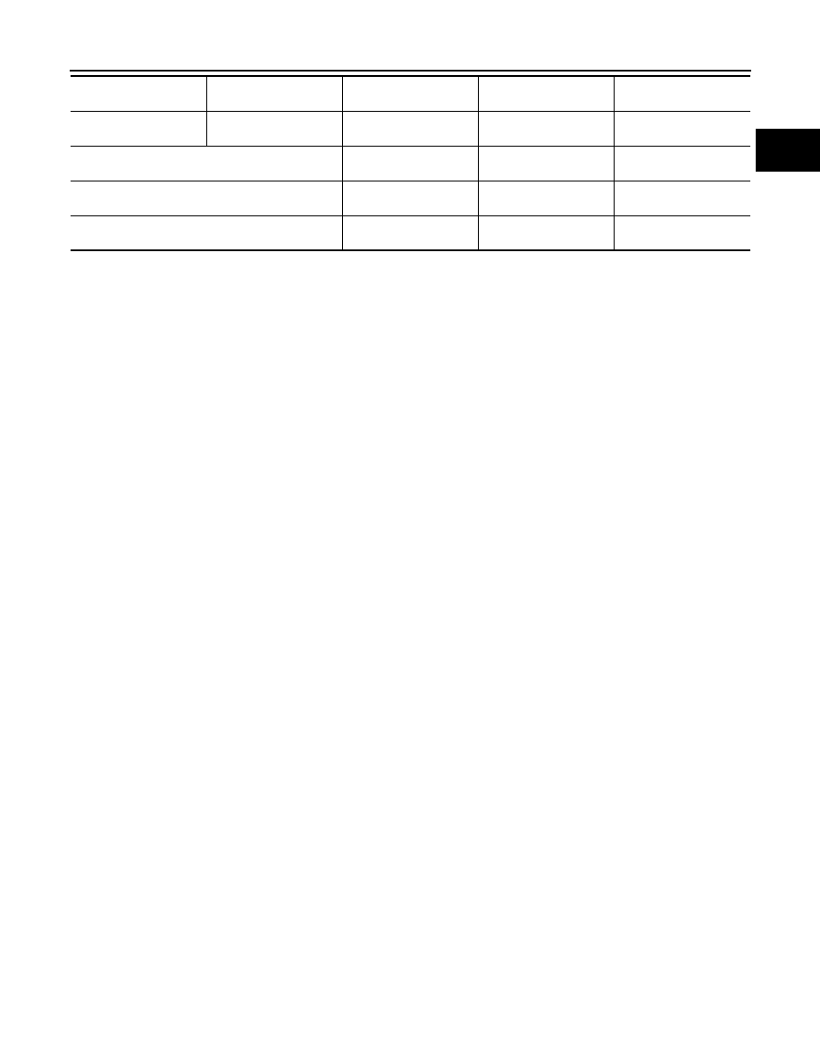
*: Power steering fluid, brake fluid, etc.

Transmission / transaxle 
fluid

AT & CVT Models

Leakage

Level / Leakage

Leakage

Transmission / transaxle 
fluid

MT Models

Level / Leakage

Leakage

Level / Leakage

Other oils and fluid*

Level

Leakage

Level

Fuel

Leakage

Leakage

Leakage

Exhaust gases

Leakage

EM-322

< UNIT DISASSEMBLY AND ASSEMBLY >

[K9K]

ENGINE STAND SETTING

UNIT DISASSEMBLY AND ASSEMBLY

ENGINE STAND SETTING

Setting

INFOID:0000000010282098

Before the engine is mounted on the engine sub-attachment, the engine's electrical harness must be removed
and the engine oil drained.

1.

Remove the drive belt. Refer to 

EM-273, "Removal and Installation"

.

2.

Remove the alternator.

3.

Remove the air conditioning compressor.

4.

Remove the multifunction support.

5.

Remove the coolant inlet pipe on the water pump.

6.

Place the rods (A), (X), (Y) on the cylinder block.

MBIB0355E

MBIB0356E

MBIB0357E

CYLINDER HEAD

EM-323

< UNIT DISASSEMBLY AND ASSEMBLY >

[K9K]

C

D

E

F

G

H

I

J

K

L

M

A

EM

N

P

O

CYLINDER HEAD

Exploded View

INFOID:0000000010282099

Removal and Installation

INFOID:0000000010282100

REMOVAL

1.

Remove the following parts.
• Engine cover.
• Air inlet tube: Refer to 

EM-281, "Exploded View"

.

• Rocker cover: Refer to 

EM-303, "Removal and Installation"

.

• Injection tube and fuel injector: Refer to 

EM-293, "Removal and Installation"

.

• High pressure supply pump: 

EM-300, "Removal and Installation"

.

• Exhaust manifold: Refer to 

EM-289, "Removal and Installation"

.

• Timing belt: Refer to 

EM-305, "Removal and Installation"

.

• Camshaft: Refer to 

EM-313, "Removal and Installation"

.

1.

Valve lifter

2.

Valve collet

3.

Valve spring retainer

4.

Valve spring

5.

Cylinder head bolt

6.

Cylinder head

7.

Cylinder head gasket

8.

Engine slinger

9.

Valve

A.

25.0 N·m (2.6 kg-m, 18ft-lb) and 255 degrees

Refer to 

GI-4, "Components"

 for symbols in the figure.

E1BIA0024GB

EM-324

< UNIT DISASSEMBLY AND ASSEMBLY >

[K9K]

CYLINDER HEAD

2.

Remove cylinder head bolts in reverse order as shown in the fig-
ure and remove cylinder head.

3.

Remove cylinder head gasket.

INSTALLATION

1.

Position the pistons at mid-stroke.

2.

Install new cylinder head gasket using the centering dowels of the cylinder block. 
NOTE:
The gasket faces (cylinder head and rocker cover) must be clean, dry and free from grease (in par-
ticular, remove finger marks).

3.

Install cylinder head and tighten cylinder head bolts in the
numerical order as shown in the figure.

4.

Turn all bolts 255 degrees clockwise (angle tightening) in the
numerical order as shown in the figure.

CAUTION:

Check and confirm the tightening angle by using the angle
wrench [SST: KV10112100 ( — )] or protractor. Avoid judg-
ment by visual inspection without the tool.

5.

Install in the reverse order of removal after this step.

Disassembly and Assembly

INFOID:0000000010282101

DISASSEMBLY

1.

Place the cylinder head on cylinder head stand [KV113B0200
(Mot. 1573) (commercial service tool) or equivalent tool].

CAUTION:

Pay strict attention to the rules regarding cleanliness. Refer
to 

EM-263, "Precaution for Diesel Equipment"

.

2.

Remove high pressure supply pump and related parts. Refer to 

EM-300, "Removal and Installation"

.

3.

Remove the injectors and glow plugs. Refer to 

EM-293, "Removal and Installation"

 and 

EM-291,

"Removal and Installation"

.

4.

Remove the vacuum pump and water outlet and thermostat assembly. Refer to 

EM-292, "Removal and

Installation"

 and 

CO-80, "Removal and Installation"

.

5.

Remove the front engine slinger, EGR assembly, air inlet pipe and exhaust manifold. Refer to 

EM-284,

"Removal and Installation"

 and 

EM-289, "Removal and Installation"

.

6.

Remove the camshaft sprocket. Refer to 

EM-313, "Removal and Installation"

.

7.

Remove the camshaft brackets. Refer to 

EM-313, "Removal and Installation"

.

E1BIA0047ZZ

: 25.0 N·m (2.6 kg-m, 18 ft-lb)

E1BIA0047ZZ

MBIB0406E

CYLINDER HEAD

EM-325

< UNIT DISASSEMBLY AND ASSEMBLY >

[K9K]

C

D

E

F

G

H

I

J

K

L

M

A

EM

N

P

O

8.

Remove the tappets, noting their position.

9.

Compress the valve springs using the valve lifter.
Remove the valve collets, valve spring retainers and valve
springs.

NOTE:
Before removing the valves and the valve stem seals, it is
vital to measure position “H” of one of the old seals in rela-
tion to the cylinder head using valve seal drift [KV113B0180
(Mot. 1511-01) (commercial service tool) or equivalent tool].

10. Install the push rod (A) of valve seal drift [KV113B0180 (Mot.

1511-01) (commercial service tool) or equivalent tool] on the
valve stem seal. 
NOTE:
The inner diameter of the push rod must be identical to that
of the valve. In addition, the bottom of the push rod must
come into contact with the metal upper section of the valve
stem seal.

MBIB0415E

MBIB0416E

MBIB0417E

MBIB0418E

EM-326

< UNIT DISASSEMBLY AND ASSEMBLY >

[K9K]

CYLINDER HEAD

11. Install the guide tube (B) over the push rod until the guide tube

comes into contact with the cylinder head, locking the push rod
with the knurled wheel. 

12. Remove the guide tube assembly plus push rod, being careful

not to loosen the knurled wheel.

13. Remove the valves and valve guide seals using the valve seal

remover [KV113B0090 (Mot. 1335) (commercial service tool) or
equivalent tool].

ASSEMBLY

1.

Install new valves and grind them gently into their respective
seats. Clean all the parts thoroughly, mark them for identification
purposes, then carry out the refitting operation.
Lubricate the inside of the valve guide.
• It is imperative to fit the valve stem seals using valve seal drift

[KV113B0180 (Mot. 1511-01) (commercial service tool) or
equivalent tool].

NOTE:
Do not lubricate the valve stem seals before fitting them.

2.

Place the valve in the cylinder head.

3.

Place the barrel of valve seal drift [KV113B0180 (Mot. 1511-01)
(commercial service tool) or equivalent tool] over the valve stem
(the inner diameter of the barrel must be identical to the diame-
ter of the valve stem).

4.

Keep the valve pressed against its seat.

5.

Place the valve stem seal (not lubricated) over the tool barrel.

MBIB0419E

MBIB0421E

MBIB0422E

MBIB0423E

CYLINDER HEAD

EM-327

< UNIT DISASSEMBLY AND ASSEMBLY >

[K9K]

C

D

E

F

G

H

I

J

K

L

M

A

EM

N

P

O

6.

Push the valve stem seal past the tool barrel, then withdraw the
barrel.

7.

Place the guide tube plus push rod assembly on the valve stem
seal.

8.

Push the valve stem seal down by tapping the top of the sleeve
with the palm of your hand until the guide tube touches the cylin-
der head.

9.

Repeat these operations for all the valves.

10. Install the valve springs and valve spring retainers using valve

spring compressor.

11. Install the valve collets using tweezers.

12. Install in the reverse order of removal after this step.

Cleaning

INFOID:0000000010282102

• It is very important not to scratch the gasket faces of any aluminum components.
• Use suitable tool to dissolve any part of the seal which remains stuck to the metal surface.
• Apply the dissolving product to the part to be cleaned, wait approximately 10 minutes, then remove it using a

wooden spatula.

• Wear gloves while carrying out this operation.
• Do not allow this dissolving product to drip on to the paintwork.
• Great care should be taken when performing this operation, to prevent foreign objects from entering

the pipes taking oil under pressure to the camshafts (pipes in both the cylinder head and its cover)
and the oil return pipes.

MBIB0424E

MBIB0425E

MBIB0416E

EM-328

< UNIT DISASSEMBLY AND ASSEMBLY >

[K9K]

CYLINDER HEAD

• Failure to follow these instructions could lead to the blocking of the oilways, resulting in rapid and

serious damage to the engine.

Inspection

INFOID:0000000010282103

INSPECTION AFTER REMOVAL

Cylinder Head Distortion

NOTE:
When performing this inspection, cylinder block distortion should be also checked. Refer to 

EM-356,

"Cylinder Block"

.

1.

Wipe off engine oil and remove water scale (like deposit), gasket, sealant, carbon, etc. with a scraper.

CAUTION:

Use utmost care not to allow gasket debris to enter passages for engine oil or water.

2.

At each of several locations on bottom surface of cylinder head, measure the distortion in six directions
using straightedge and feeler gauge.

• If it exceeds the limit, replace cylinder head.

Cylinder Head Height

Measure the height of cylinder head (H).

Valve protrusion

Check the valve protrusion using dial gauge stand set [KV113B0040
(Mot.251-01) (commercial service tool) or equivalent tool] and dial
gauge stand set [KV113B0050 (Mot.252-01) (commercial service
tool) or equivalent tool] as shown.

INSPECTION AFTER DISASSEMBLY

Valve

Measure the valves as follows.
• Stem diameter (d)

• Face angle (

α

)

Limit

: Refer to 

EM-354, "Cylinder Head"

.

Standard

: Refer to 

EM-354, "Cylinder Head"

.

E1BIA0063ZZ

Standard

0.07 to 0.07 mm (

0.0028 to 0.0028 in)

MBIB0426E

Intake

: Refer to 

EM-354, "Cylinder Head"

Exhaust

: Refer to 

EM-354, "Cylinder Head"

Intake

: Refer to 

EM-354, "Cylinder Head"

Exhaust

: Refer to 

EM-354, "Cylinder Head"

E1BIA0064ZZ

CYLINDER HEAD

EM-329

< UNIT DISASSEMBLY AND ASSEMBLY >

[K9K]

C

D

E

F

G

H

I

J

K

L

M

A

EM

N

P

O

• Head diameter (D)

• Valve length (L)

• Valve margin (T)

Valve Seat

Measure the valve seats as follows.
• Seat angle (

α

)

• Contacting width (X)

• Seat outer diameter (D):

• Cylinder head seat recess diameter (D)

Valve Guide Clearance

1.

Measure diameter of valve stem with micrometer.

2.

Measure inner diameter of valve guide with inside micrometer.

3.

Calculate the valve guide clearance.
(Valve guide clearance) = (Valve guide inner diameter) – (Valve
stem diameter)

• If it exceeds the limit, replace and/or valve guide.

Valve Spring

Intake

: Refer to 

EM-354, "Cylinder Head"

Exhaust

: Refer to 

EM-354, "Cylinder Head"

Intake

: Refer to 

EM-354, "Cylinder Head"

Exhaust

: Refer to 

EM-354, "Cylinder Head"

Intake

: Refer to 

EM-354, "Cylinder Head"

Exhaust

: Refer to 

EM-354, "Cylinder Head"

Intake

: Refer to 

EM-354, "Cylinder Head"

Exhaust

: Refer to 

EM-354, "Cylinder Head"

Intake

: Refer to 

EM-354, "Cylinder Head"

Exhaust

: Refer to 

EM-354, "Cylinder Head"

Intake

: Refer to 

EM-354, "Cylinder Head"

Exhaust

: Refer to 

EM-354, "Cylinder Head"

Intake

: Refer to 

EM-354, "Cylinder Head"

Exhaust

: Refer to 

EM-354, "Cylinder Head"

E1BIA0066ZZ

Intake

: 0.020 - 0.050 mm (0.0008 - 0.0020 in)

Exhaust

: 0.030 - 0.063 mm (0.0012 - 0.0025 in)

SEM938C

EM-330

< UNIT DISASSEMBLY AND ASSEMBLY >

[K9K]

CYLINDER HEAD

Measure the valve spring as follows.
• Free height

• Length under load

• Full pressed height

• Wire diameter

• Inner diameter

• Outer diameter

• Squareness

Intake and exhaust

: Refer to 

EM-354, "Cylinder Head"

Intake and exhaust

: Refer to 

EM-354, "Cylinder Head"

Intake and exhaust

: Refer to 

EM-354, "Cylinder Head"

Intake and exhaust

: Refer to 

EM-354, "Cylinder Head"

Intake and exhaust

: Refer to 

EM-354, "Cylinder Head"

Intake and exhaust

: Refer to 

EM-354, "Cylinder Head"

Intake and exhaust

: Refer to 

EM-354, "Cylinder Head"

SEM113

CYLINDER BLOCK

EM-331

< UNIT DISASSEMBLY AND ASSEMBLY >

[K9K]

C

D

E

F

G

H

I

J

K

L

M

A

EM

N

P

O

CYLINDER BLOCK

Exploded View

INFOID:0000000010282104

Disassembly and Assembly

INFOID:0000000010282105

DISASSEMBLY

E1BIA1217GB

1.

Oil seal

2.

Crankshaft cover

3.

Gasket

4.

Cylinder block

5.

Oil seal

6

TDC pin plug

7.

Top ring

8.

Second ring

9.

Oil ring

10. Piston

11.

Piston pin

12. Snap ring

13. Connecting rod

14. Crankshaft pulley bolt

15. Crankshaft pulley

16. Crankshaft sprocket (timing belt)

17.

Crankshaft sprocket (oil pump drive 
chain)

18. Crankshaft

19. Pilot bushing

20. Flywheel

21. Reinforcement plate

A.

25.0 N·m (2.6 kg-m, 18 ft-lb) and 47 degrees

B.

20.0 N·m (2.0 kg-m, 15 ft-lb) and 45 degrees

C.

120.0 N·m (12 kg-m, 89 ft-lb) and 95 degrees

D.

20.0 N·m (2.0 kg-m, 15 ft-lb) and 36 degrees

Refer to 

GI-4, "Components"

 for symbols in the figure.

EM-332

< UNIT DISASSEMBLY AND ASSEMBLY >

[K9K]

CYLINDER BLOCK

1.

Install the ring gear stopper [SST: KV113B0060 (Mot. 582-01)].

2.

Remove the clutch housing.

3.

Remove the flywheel.

4.

Remove the oil pan bolt in reverse order as shown.

5.

Remove the oil level sensor.

6.

Remove the oil pump.

7.

Remove the crankshaft cover.

8.

Remove the water pump.

MBIB0397E

MBIB0439E

MBIB1257E

MBIB0442E

MBIB0443E

CYLINDER BLOCK

EM-333

< UNIT DISASSEMBLY AND ASSEMBLY >

[K9K]

C

D

E

F

G

H

I

J

K

L

M

A

EM

N

P

O

9.

Remove the oil pump chain.

10. Remove the oil pump drive sprocket.

WARNING:

Do not use a sharp point to mark the bearing caps in rela-
tion to their connecting rods to avoid starting a crack in the
rod. Use a permanent marker pen. 

11. Remove the big end cap bolts and the connecting rod/piston

assemblies.
NOTE:
It is essential to mark the position of the main bearing cap,
as the category may be different for each bearing.

12. Remove the main bearing caps.

13. Remove the crankshaft.

14. Remove the oil pressure switch, the knock sensor and oil filter

bracket connecting bolt.

15. Remove the oil cooler connecting bolt.

MBIB0444E

MBIB0341E

MBIB0445E

MBIB0446E

EM-334

< UNIT DISASSEMBLY AND ASSEMBLY >

[K9K]

CYLINDER BLOCK

16. To remove the oil jets (A), they must be drilled with a 7 mm (0.28

in) diameter drill. This is necessary in order to remove the spring
stop (B) and the spring (C).

NOTE:
Do not remove the ball (D) to prevent from entering the
cooling circuit.

17. Remove the using a suitable brush.

18. Screw oil jet remover [SST: KV113B0120 (Mot. 1485-01)] in the

drilled out jets using a 6 mm (0.24 in) Allen key which must slide
into the tool.

MBIB0447E

MBIB0448E

MBIB0449E

MBIB0450E

CYLINDER BLOCK

EM-335

< UNIT DISASSEMBLY AND ASSEMBLY >

[K9K]

C

D

E

F

G

H

I

J

K

L

M

A

EM

N

P

O

19. Screw sliding hammer [SST: KV113B0020 (Emb. 880)] onto oil

jet remover [SST: KV113B0120 (Mot. 1485-01)] and remove the
oil jet.

20. To remove the piston pin, remove the snap ring using a screwdriver, then release the pin.

Removing the Piston Pins

NOTE:
It is imperative to mark the connecting rod to match it to its piston, because the piston height classes
in the same engine may be different (see Technical Specifications section).

ASSEMBLY

1.

The oil jets must be installed using oil jet remover plate [SST: KV113B0170 (Mot. 1494)].

2.

Install oil jets for NO. 1 and NO. 3 cylinders with the following procedure.

a.

Install plate (A) of oil jet remover plate [SST: KV113B0170 (Mot. 1494)] onto the cylinder block (as shown
in the figure) without tightening the two bolts (C).

b.

Position the guide rod (B) in the plate (A) and the end of the guide rod in the hole of the oil jet to center the
plate (A).

c.

Tighten the two bolts (C).

d.

Remove the guide rod.

e.

Install the push rod instead of the guide rod, then insert the oil jet
into the push rod.
NOTE:
Check that the oil jet is correctly oriented with the end of
the jet (D) directed towards the center of the cylinder.

f.

With a hammer, tap the push rod until the shoulder (E) of the
push rod comes into contact with the plate (A).

3.

Install oil jets for NO. 1 and NO.4 cylinders with the following procedure.

MBIB0451E

MBIB0453E

MBIB0454E

EM-336

< UNIT DISASSEMBLY AND ASSEMBLY >

[K9K]

CYLINDER BLOCK

a.

Fit plate (A) of oil jet remover plate [SST: KV113B0170 (Mot.
1494)] onto the cylinder block (as shown in the figure) without
tightening the two bolts (C).

b.

Position the guide rod (B) in the plate (A) and the end of the guide rod in the hole of the oil jet to center the
plate (A).

c.

Tighten the two bolts (C).

d.

Remove the guide rod.

e.

Position the push rod instead of the guide rod, then insert the oil
jet into the push rod.
NOTE:
Check that the oil jet is correctly oriented with the end of
the jet (D) directed towards the center of the cylinder.

f.

With a hammer, tap the push rod until the shoulder (E) of the
push rod comes into contact with the plate (A).

4.

Check orientation of the oil jets (see diagram below).

5.

Clean the cylinder block and crankshaft by passing a wire
through the lubrication channels.

6.

Install oil level gauge guide tube.

7.

Select main bearing with the following procedure.

a.

Identify the category of crankshaft main journal diameter (A) with checking the marking of crankshaft as
shown in the figure.
NOTE:

MBIB0455E

MBIB0453E

MBIB0456E

A

Orientation of the oil jets of No. 2 and No. 4 cylinders

B

Orientation of the oil jets of No. 1 and No. 3 cylinders

MBIB0457E


Content      ..     19      20      21      22     ..