Qashqai J11. Engine mechanical (HRA2DDT, K9K, MR20DD) - part 20
TIMING BELT
EM-305
< REMOVAL AND INSTALLATION >
[K9K]
C
D
E
F
G
H
I
J
K
L
M
A
EM
N
P
O
TIMING BELT
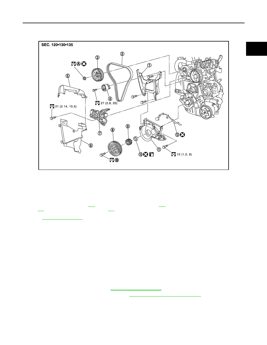
Exploded View
INFOID:0000000010287219
Refert to
for symbol marks in the figure
Removal and Installation
INFOID:0000000010287220
CAUTION:
• Apply new engine oil to parts marked in illustration before installation.
• Replace any belt that has been removed.
• Never turn the engine in the direction opposite to that of normal operation.
• When replacing the timing belt, be sure to replace the timing belt tensioner.
• Never run the engine without the drive belts to avoid damaging the crankshaft pulley.
REMOVAL
1.
Disconnect battery cable from the negative terminal.
2.
Remove front wheel RH.
3.
Remove fender protector RH. Refer to
4.
Remove drive belt, and auto-tensioner. Refer to
EM-273, "Removal and Installation"
5.
Remove RH engine torque rod.
JPBIA3140GB
1.
Timing belt inner cover
2.
Timing belt
3.
Camshaft sprocket
4.
Timing belt tensioner
5.
Timing belt upper cover
6.
Timing belt lower cover
7.
Cylinder head suspended bracket
8.
Crankshaft pulley
9.
Crankshaft sprocket
10. Rear oil seal
11.
Rear oil seal retainer
12. Gasket
A
Comply with the assembly proce-
dure when tightening. Refer to
B
Comply with the assembly proce-
dure when tightening. Refer to