Qashqai J11. Engine mechanical (HRA2DDT, K9K, MR20DD) - part 19
EXHAUST MANIFOLD
EM-289
< REMOVAL AND INSTALLATION >
[K9K]
C
D
E
F
G
H
I
J
K
L
M
A
EM
N
P
O
EXHAUST MANIFOLD
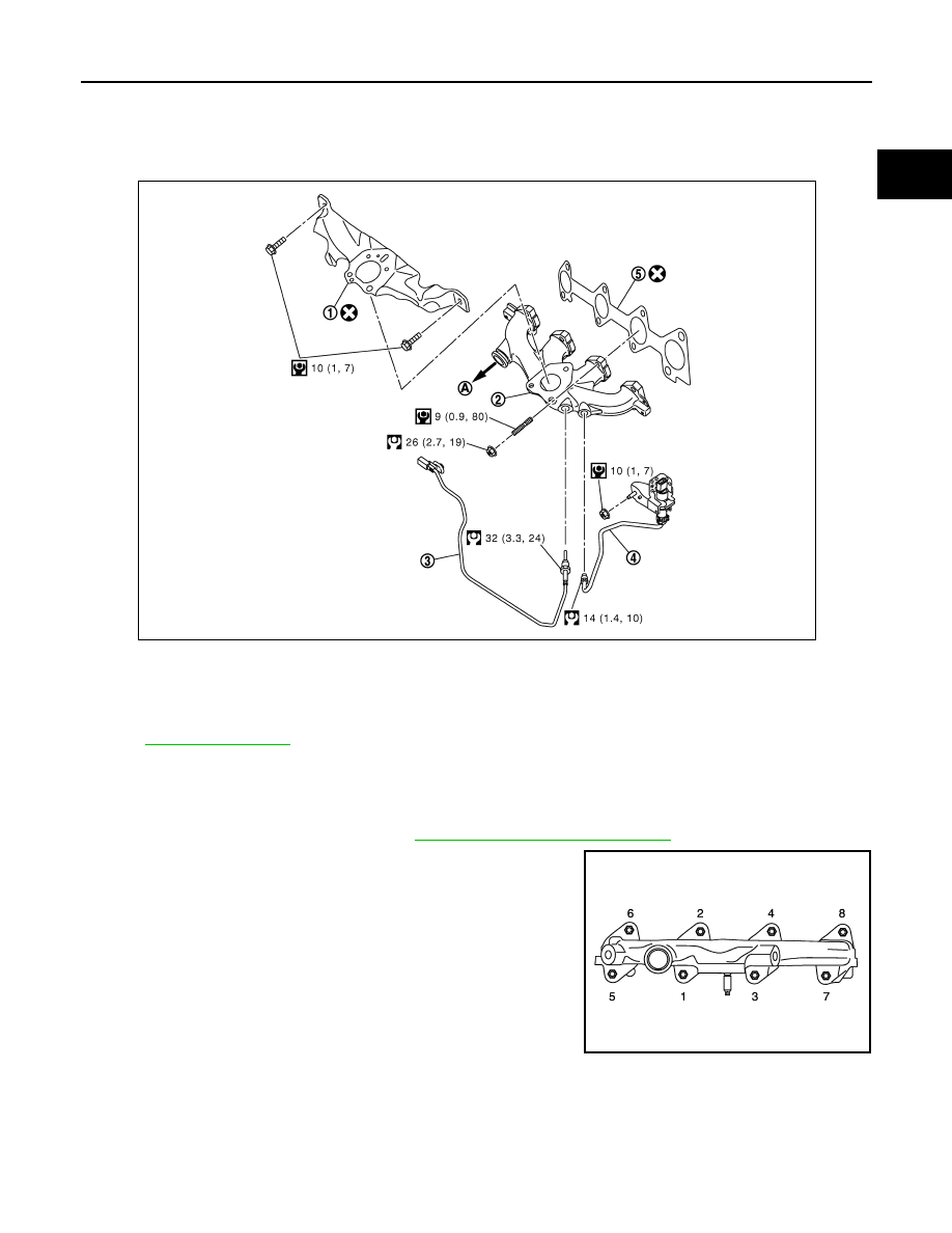
Exploded View
INFOID:0000000010287205
for symbol marks in the figure.
Removal and Installation
INFOID:0000000010282072
REMOVAL
1.
Remove turbocharger assembly. Refer to
EM-287, "Removal and Installation"
2.
Loosen exhaust manifold mounting nuts in the reverse order as
shown. Then remove exhaust manifold.
CAUTION:
Be careful not to deform each turbocharger piping when pulling
out the assembly.
INSTALLATION
1.
Clean the surface of exhaust manifold and cylinder head.
2.
Install new gasket to cylinder head.
1.
Gasket
2.
Exhaust manifold
3.
Exhaust gas temperature sensor 1
4.
Exhaust gas pressure sensor 1
5.
Gasket
A.
To high pressure EGR pipe
E1BIA0886GB
JPBIA3039ZZ