Qashqai J11. Engine mechanical (HRA2DDT, K9K, MR20DD) - part 17
SERVICE DATA AND SPECIFICATIONS (SDS)
EM-257
< SERVICE DATA AND SPECIFICATIONS (SDS)
[MR20DD]
C
D
E
F
G
H
I
J
K
L
M
A
EM
N
P
O
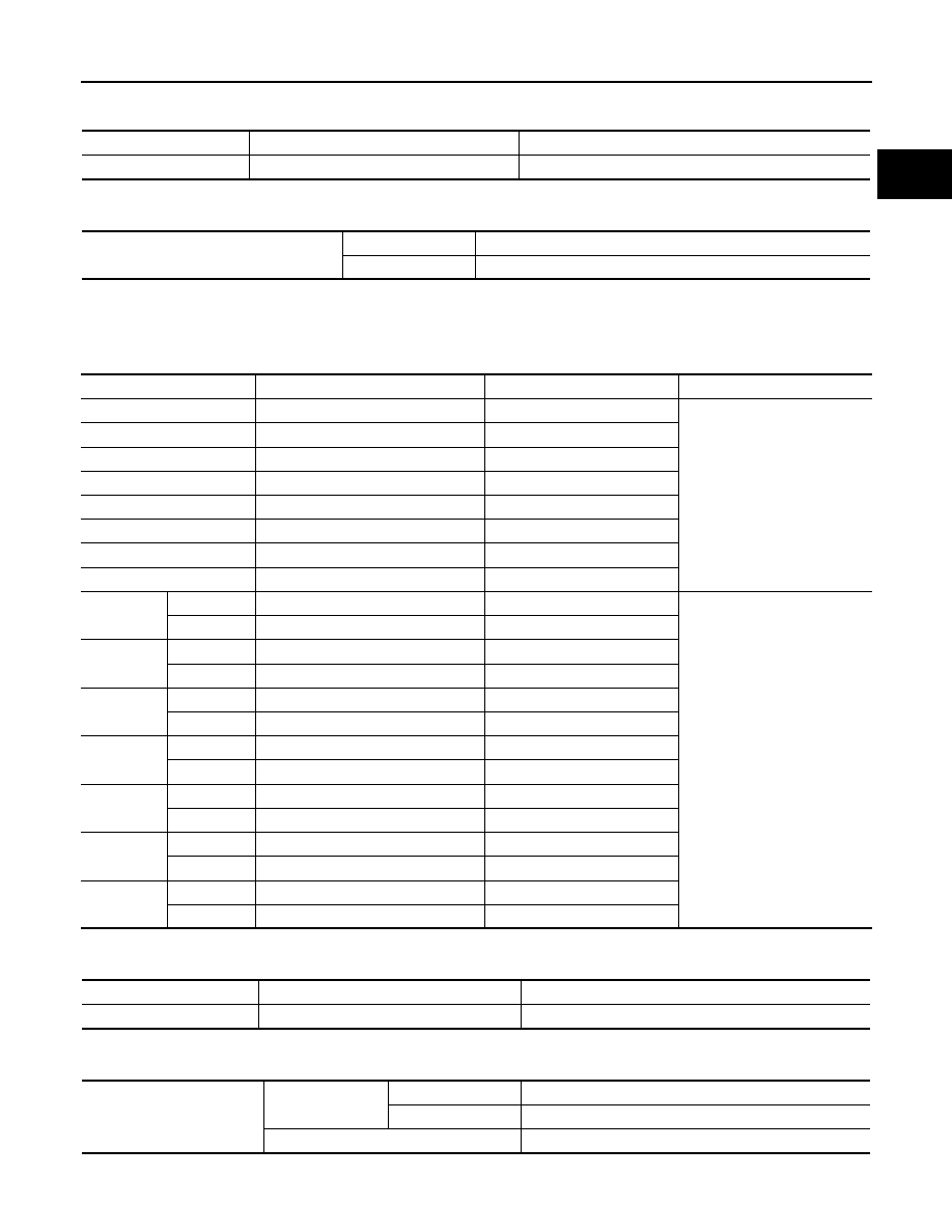
UNDERSIZE TABLE
Unit: mm (in)
CONNECTING ROD BEARING OIL CLEARANCE
Unit: mm (in)
Main Bearing
INFOID:0000000010735685
MAIN BEARING GRADE TABLE (ALL JOURNALS)
Unit: mm (in)
UNDERSIZE TABLE
Unit: mm (in)
MAIN BEARING OIL CLEARANCE
Unit: mm (in)
Items
Thickness
Crank pin journal diameter
US 0.25 (0.0098)
1.623 - 1.631 (0.0639 - 0.0642)
Grind so that bearing clearance is the specified value.
Connecting rod bearing oil clearance
Standard
0.037 - 0.047 (0.0015 - 0.0019)
Limit
0.07 (0.0028)
Grade number
Thickness
Identification color
Remarks
0
1.996 - 1.999 (0.0786 - 0.0787)
Black - Black
Grade and color are the same
for upper and lower bearings.
1
1.999 - 2.002 (0.0787 - 0.0788)
Brown - Brown
2
2.002 - 2.005 (0.0788 - 0.0789)
Green - Green
3
2.005 - 2.008 (0.0789 - 0.0791)
Yellow - Yellow
4
2.008 - 2.011 (0.0791 - 0.0792)
Blue - Blue
5
2.011 - 2.014 (0.0792 - 0.0793)
Pink - Pink
6
2.014 - 2.017 (0.0793 - 0.0794)
Purple - Purple
7
2.017 - 2.020 (0.0794 - 0.0795)
White - White
01
UPR
1.996 - 1.999 (0.0786 - 0.0787)
Black - Black
Grade and color are different
between upper and lower bear-
ings.
LWR
1.999 - 2.002 (0.0787 - 0.0788)
Brown - Brown
12
UPR
1.999 - 2.002 (0.0787 - 0.0788)
Brown - Brown
LWR
2.002 - 2.005 (0.0788 - 0.0789)
Green - Green
23
UPR
2.002 - 2.005 (0.0788 - 0.0789)
Green - Green
LWR
2.005 - 2.008 (0.0789 - 0.0791)
Yellow - Yellow
34
UPR
2.005 - 2.008 (0.0789 - 0.0791)
Yellow - Yellow
LWR
2.008 - 2.011 (0.0791 - 0.0792)
Blue - Blue
45
UPR
2.008 - 2.011 (0.0791 - 0.0792)
Blue - Blue
LWR
2.011 - 2.014 (0.0792 - 0.0793)
Pink - Pink
56
UPR
2.011 - 2.014 (0.0792 - 0.0793)
Pink - Pink
LWR
2.014 - 2.017 (0.0793 - 0.0794)
Purple - Purple
67
UPR
2.014 - 2.017 (0.0793 - 0.0794)
Purple - Purple
LWR
2.017 - 2.020 (0.0794 - 0.0795)
White - White
Items
Thickness
Main journal diameter
US 0.25 (0.0098)
2.126 - 2.134 (0.0837 - 0.0840)
Grind so that bearing clearance is the specified value.
Main bearing oil clearance
Standard
No. 1 and 4
0.024 - 0.034 (0.0009 - 0.0013)
No. 2, 3 and 5
0.012 - 0.022 (0.0005 - 0.0009)
Limit
0.065 (0.0026)