Qashqai J11. Engine mechanical (HRA2DDT, K9K, MR20DD) - part 24
PREPARATION
EM-369
< PREPARATION >
[R9M]
C
D
E
F
G
H
I
J
K
L
M
A
EM
N
P
O
PREPARATION
PREPARATION
Special Service Tools
INFOID:0000000010281961
NISSAN tool number
(RENAULT tool No.)
Tool name
Description
—
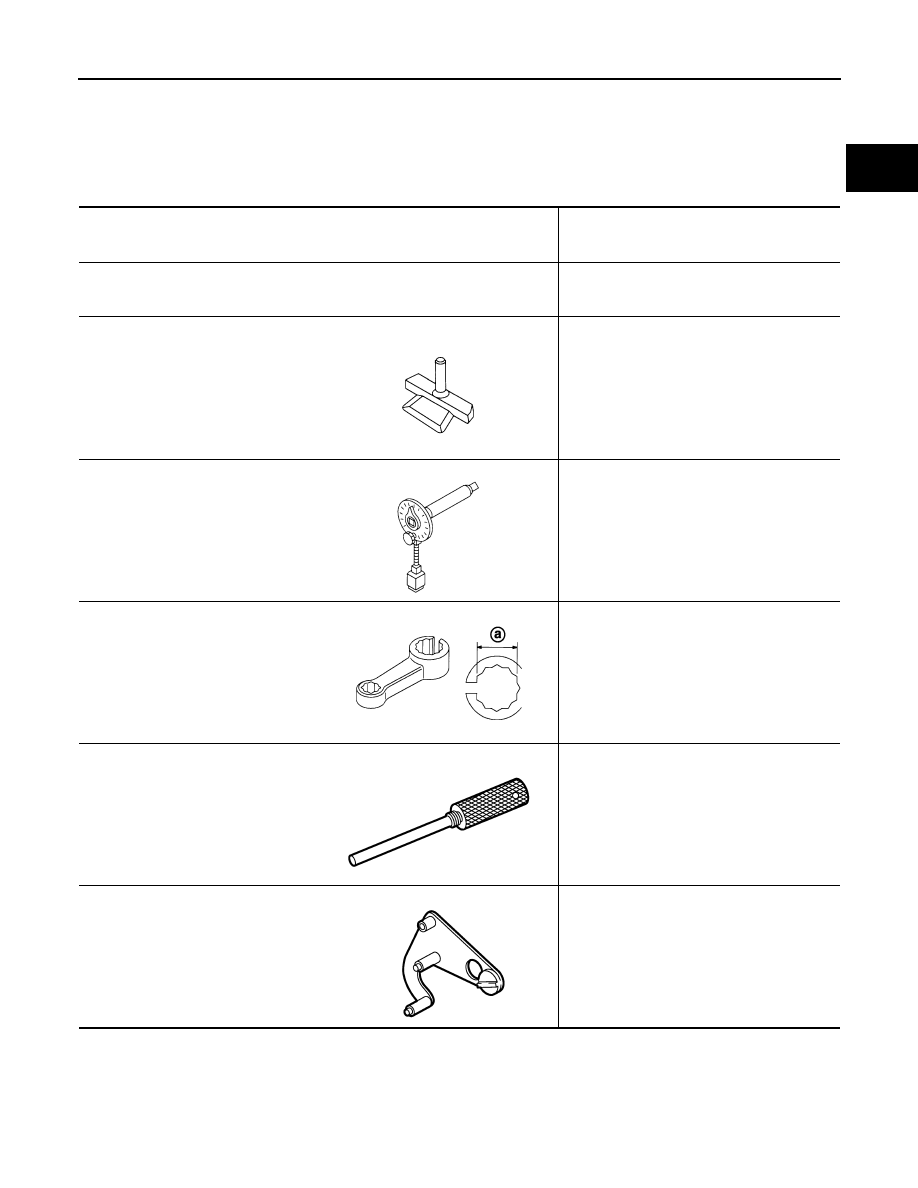
(Mot. 1979)
Piston ring compressor
Installing piston assembly into cylinder bore
KV10111100
(
—
)
Seal cutter
Removing oil pan and front cover. etc
KV10112100
(
—
)
Angle wrench
Tightening bolts for bearing cap, cylinder
head, etc. in angle
KV10114400
(
—
)
Heated oxygen sensor wrench
Loosening or tightening air fuel ratio sensor
a: 22 mm (0.87 in)
—
(Mot. 1970)
TDC set pin
To lock engine at TDC
—
(Mot. 1969)
Camshaft timing tool
To lock camshaft when changing timing chain
NT046
NT014
JPBIA0397ZZ
JPBIA0629ZZ
JPBIA0628ZZ