Qashqai J11. Engine control system (MR20DD) - part 12


  Index      Nissan     Qashqai J11. Engine control system (MR20DD). Service and Repair Manual


Search            copyright infringement  


Content      ..     10      11      12      13     ..


Qashqai J11. Engine control system (MR20DD) - part 12


ECM-178

< DTC/CIRCUIT DIAGNOSIS >

[MR20DD]

P0087, P0088, P0090 FRP CONTROL SYSTEM

Is the inspection result normal?

YES

>> GO TO 2.

NO

>> Replace high pressure fuel pump. Refer to  

EM-159, "Removal and Installation"

.

2.

CHECK HIGH PRESSURE FUEL PUMP-2

WITH CONSULT

1.

Reconnect high pressure fuel pump harness connector.

2.

Start the engine.

3.

Check “FUEL PRES SEN” in “DATA MONITOR” of “ENGINE” with CONSULT.

WITHOUT CONSULT

1.

Start the engine.

2.

Check fuel rail pressure sensor signal voltage.

Is the inspection result normal?

YES

>> INSPECTION END

NO

>> Replace high pressure fuel pump. Refer to  

EM-159, "Removal and Installation"

.

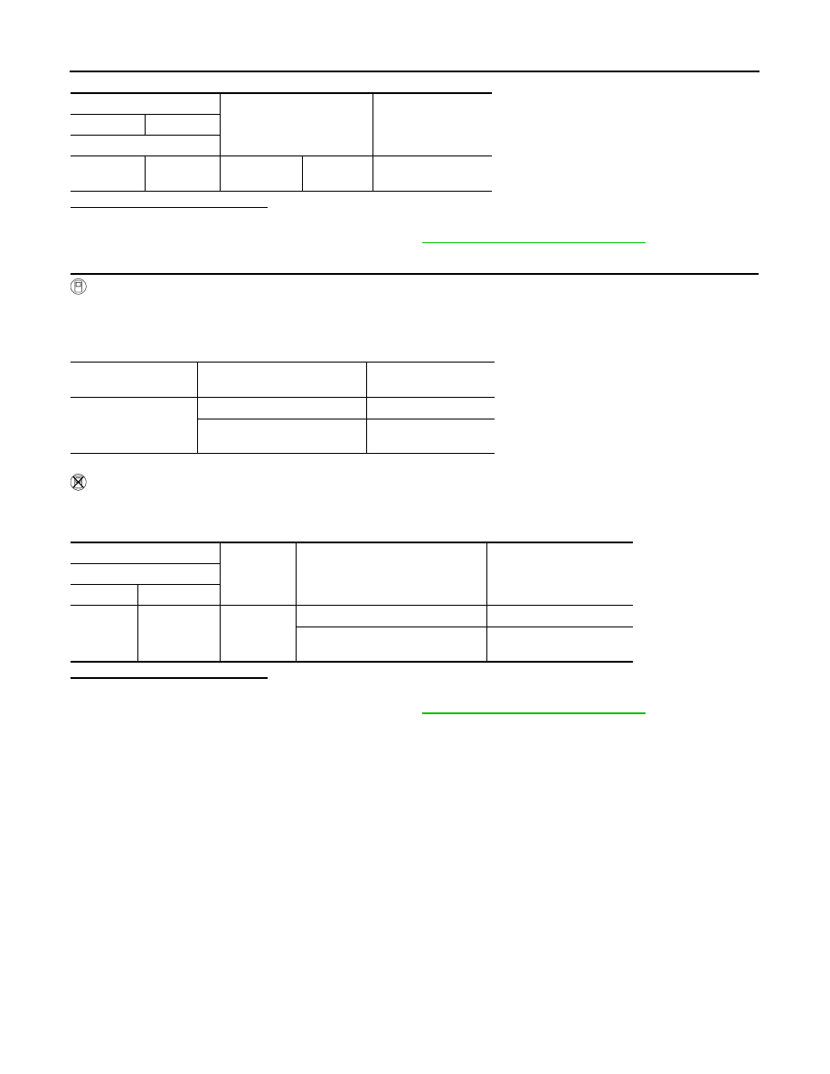
High pressure fuel pump

Condition

Resistance

+

Terminal

1

2

Temperature 

°

C (

°

F)

20 – 30 (68 
– 86)

0.46 - 0.51 

Data monitor item

Condition

Voltage

(Approx.)

FUEL PRES SEN V

Engine speed: idle

820 – 1,140 mV

Engine speed: Revving engine 
from idle to 4,000 rpm

820 – 2,900 mV

+

Ground

Condition

Voltage

(Approx.)

Fuel rail pressure sensor

Connector

Terminal

F95

2

Ground

Engine speed: idle

0.82 – 1.14 V

Engine speed: Revving engine 
from idle to 4,000 rpm

0.82 – 2.9 V

P0102, P0103 MAF SENSOR

ECM-179

< DTC/CIRCUIT DIAGNOSIS >

[MR20DD]

C

D

E

F

G

H

I

J

K

L

M

A

ECM

N

P

O

P0102, P0103 MAF SENSOR

DTC Description

INFOID:0000000010702906

DTC DETECTION LOGIC

POSSIBLE CAUSE

P0102

• Harness or connectors [The mass air flow sensor (bank 1) circuit is open or shorted.]
• Intake air leaks
• Mass air flow sensor

P0103

• Harness or connectors [The mass air flow sensor (bank 1) circuit is open or shorted.]
• Mass air flow sensor

FAIL-SAFE

DTC CONFIRMATION PROCEDURE

1.

PRECONDITIONING

DTC No.

CONSULT screen terms

(Trouble diagnosis content)

DTC detecting condition

P0102

MAF SEN/CIRCUIT-B1
(Mass or volume air flow “A” circuit low)

An excessively low voltage from the sensor is sent to ECM during engine 
running.

P0103

MAF SEN/CIRCUIT-B1
(Mass or volume air flow “A” circuit high)

An excessively high voltage from the sensor is sent to ECM.

Engine operating condition in fail-safe mode

Fail safe mode

Vehicle behavior

Traveling con-
trol mode

Accelerator an-
gle variation 
control

ECM controls the accelerator pedal depression speed to make it slower than actual speed. This 
causes a drop in accelerating performance and encourages the driver to repair malfunction.
NOTE:
ECM does not control the accelerator pedal releasing speed.

Engine output 
control

ECM reduces the engine output, according to the rise in engine speed. This reduces the vehicle 
speed to encourage the driver to repair malfunction.

Device fix mode

• This mode fixes the IVT control solenoid valve and the EVT control solenoid valve in the refer-

ence position.

• The intake manifold runner control valve motor is turned OFF (intake manifold runner control 

valve opens).

Combustion 
control mode

Stratified charge 
combustion 
control at start-
ing

No stratified charge combustion at starting (cold start).

Idle speed con-
trol

Stops feedback control of idle speed and controls with specified speed.

Recovery speed 
control at decel-
erating

Stops recovery speed control by the fuel cut at decelerating and controls with specified speed.

Idle neutral con-
trol

Stops idle neutral control.

Ignition timing 
correction con-
trol

Partially controls ignition timing control.

Retardation 
control

Controls ignition timing delay control in the intermediate water temperature range.

ECM-180

< DTC/CIRCUIT DIAGNOSIS >

[MR20DD]

P0102, P0103 MAF SENSOR

If DTC Confirmation Procedure has been previously conducted, always turn ignition switch OFF and wait at
least 10 seconds before conducting the next test.
Which DTC is detected?

P0102 >> GO TO 2.
P0103 >> GO TO 3.

2.

DTC CONFIRMATION PROCEDURE-DTC P0102

1.

Start engine and let it idle at least 5 seconds.

2.

Check DTC.

Is DTC detected?

YES

>> Proceed to 

ECM-180, "Diagnosis Procedure"

.

NO

>> INSPECTION END

3.

DTC CONFIRMATION PROCEDURE-P0103-1

1.

Turn ignition switch ON and wait at least 5 seconds.

2.

Check DTC.

Is DTC detected?

YES

>> Proceed to 

ECM-180, "Diagnosis Procedure"

.

NO

>> GO TO 4.

4.

DTC CONFIRMATION PROCEDURE-DTC P0103-2

1.

Turn ignition switch OFF and wait at least 10 seconds.

2.

Start engine and let it idle at least 5 seconds.

3.

Check DTC.

Is DTC detected?

YES

>> Proceed to 

ECM-180, "Diagnosis Procedure"

.

NO-1

>> To check malfunction symptom before repair: Refer to 

GI-41, "Intermittent Incident"

.

NO-2

>> Confirmation after repair: INSPECTION END

Diagnosis Procedure

INFOID:0000000010702907

1.

INSPECTION START

Confirm the detected DTC. Refer to 

ECM-179, "DTC Description"

.

Which DTC is detected?

P0102 >> GO TO 2.
P0103 >> GO TO 3.

2.

CHECK INTAKE SYSTEM

Check the following for connection.
• Air duct
• Vacuum hoses
• Intake air passage between air duct to intake manifold

Is the inspection result normal?

YES

>> GO TO 3.

NO

>> Reconnect the parts.

3.

CHECK MASS AIR FLOW SENSOR POWER SUPPLY

1.

Turn ignition switch OFF.

2.

Disconnect mass air flow (MAF) sensor harness connector.

3.

Turn ignition switch ON.

4.

Check the voltage between mass air flow (MAF) sensor harness connector and ground.

+

Ground

Voltage

MAF sensor

Connector

Terminal

F73

5

Ground

Battery voltage

P0102, P0103 MAF SENSOR

ECM-181

< DTC/CIRCUIT DIAGNOSIS >

[MR20DD]

C

D

E

F

G

H

I

J

K

L

M

A

ECM

N

P

O

Is the inspection result normal?

YES

>> GO TO 5.

NO

>> GO TO 4.

4.

CHECK MASS AIR FLOW SENSOR POWER SUPPLY CIRCUIT

1.

Turn ignition switch OFF.

2.

Disconnect IPDM E/R harness connector.

3.

Check the continuity between mass air flow (MAF) sensor harness connector and IPDM E/R harness con-
nector.

4.

Also check harness for short to ground and short to power.

Is the inspection result normal?

YES

>> Perform trouble diagnosis for power supply circuit.

NO

>> Repair or replace malfunctioning part.

5.

CHECK MASS AIR FLOW SENSOR GROUND CIRCUIT FOR OPEN AND SHORT

1.

Turn ignition switch OFF.

2.

Disconnect ECM harness connector.

3.

Check the continuity between mass air flow (MAF) sensor harness connector and ECM harness connec-
tor.

4.

Also check harness for short to ground and short to power.

Is the inspection result normal?

YES

>> GO TO 6.

NO

>> Repair or replace malfunctioning part.

6.

CHECK MASS AIR FLOW SENSOR INPUT SIGNAL CIRCUIT FOR OPEN AND SHORT

1.

Check the continuity between mass air flow (MAF) sensor harness connector and ECM harness connec-
tor.

2.

Also check harness for short to ground and short to power.

Is the inspection result normal?

YES

>> GO TO 7.

NO

>> Repair or replace malfunctioning part.

7.

CHECK INTAKE AIR TEMPERATURE SENSOR

Refer to 

ECM-190, "Component Inspection"

.

Is the inspection result normal?

YES

>> GO TO 8.

NO

>> Replace mass air flow (MAF) sensor (with intake air temperature sensor). Refer to 

EM-147,

"Removal and Installation"

.

+

Continuity

MAF sensor

IPDM E/R

Connector

Terminal

Connector

Terminal

F73

5

F90

103

Existed

+

Continuity

MAF sensor

ECM

Connector

Terminal

Connector

Terminal

F73

4

F15

20

Existed

+

Continuity

MAF sensor

ECM

Connector

Terminal

Connector

Terminal

F73

3

F15

28

Existed

ECM-182

< DTC/CIRCUIT DIAGNOSIS >

[MR20DD]

P0102, P0103 MAF SENSOR

8.

CHECK MASS AIR FLOW SENSOR

Refer to 

ECM-182, "Component Inspection"

.

Is the inspection result normal?

YES

>> INSPECTION END

NO

>> Replace mass air flow (MAF) sensor. Refer to 

EM-147, "Removal and Installation"

.

Component Inspection

INFOID:0000000010702908

1.

CHECK MASS AIR FLOW SENSOR-1

WITH CONSULT

1.

Turn ignition switch OFF.

2.

Reconnect all harness connectors disconnected.

3.

Start engine and warm it up to normal operating temperature.

4.

Select “MAS A/F SE-B1” in “DATE MONITOR” of “ENGINE” with CONSULT and check the indication
under the following condition.

*: Check for linear voltage rise in response to increase of engine speed.

WITHOUT CONSULT

1.

Turn ignition switch OFF.

2.

Reconnect all harness connectors disconnected.

3.

Start engine and warm it up to normal operating temperature.

4.

Check the voltage between ECM harness connector terminals under the following conditions.

*: Check for linear voltage rise in response to increase of engine speed.

Is the inspection result normal?

YES

>> INSPECTION END

NO

>> GO TO 2.

2.

CHECK FOR THE CAUSE OF UNEVEN AIR FLOW THROUGH INTAKE AIR DUCT

1.

Turn ignition switch OFF.

2.

Check for the cause of uneven air flow through intake air duct. Refer to the following.

-

Crushed air ducts

-

Malfunctioning seal of air cleaner element

-

Uneven dirt like leaves or insects of air cleaner element

-

Intake valve deposit

-

Improper specification of intake air system parts

Is the inspection result normal?

YES

>> GO TO 4.

NO

>> GO TO 3.

3.

CHECK MASS AIR FLOW SENSOR-2

WITH CONSULT

Monitor item

Condition

Indication

MAS A/F SE-B1

Ignition switch ON (Engine stopped.)

Approx. 0.4 V

Idle (Engine is warmed-up to normal op-
erating temperature.)

0.7 -1.2 V

Idle to about 4,000 rpm

0.7 -1.2 V 

 2.4 V*

ECM

Condition

Voltage

Connector

+

Terminal

F15

28

20

Ignition switch ON (Engine stopped.)

Approx. 0.4 V

Idle (Engine is warmed-up to normal 
operating temperature.)

0.7 -1.2 V

Idle to about 4,000 rpm

0.7 -1.2 V 

 2.4 V*

P0102, P0103 MAF SENSOR

ECM-183

< DTC/CIRCUIT DIAGNOSIS >

[MR20DD]

C

D

E

F

G

H

I

J

K

L

M

A

ECM

N

P

O

1.

Repair malfunctioning part.

2.

Start engine and warm it up to normal operating temperature.

3.

Select “MAS A/F SE-B1” in “DATE MONITOR” of “ENGINE” with CONSULT and check the indication
under the following condition.

*: Check for linear voltage rise in response to increase of engine speed.

WITHOUT CONSULT

1.

Repair malfunctioning part.

2.

Start engine and warm it up to normal operating temperature.

3.

Check the voltage between ECM harness connector terminals under the following conditions.

*: Check for linear voltage rise in response to increase of engine speed.

Is the inspection result normal?

YES

>> INSPECTION END

NO

>> GO TO 4.

4.

CHECK AIR FLOW SENSOR

WITH CONSULT

1.

Turn ignition switch OFF.

2.

Reconnect all harness connectors disconnected.

3.

Start engine and warm it up to normal operating temperature.

4.

Select “MAS A/F SE-B1” in “DATE MONITOR” of “ENGINE” with CONSULT and check the indication
under the following condition.

*: Check for linear voltage rise in response to increase of engine speed.

WITHOUT CONSULT

1.

Turn ignition switch OFF.

2.

Reconnect all harness connectors disconnected.

3.

Start engine and warm it up to normal operating temperature.

4.

Check the voltage between ECM harness connector terminals under the following conditions.

Monitor item

Condition

Indication

MAS A/F SE-B1

Ignition switch ON (Engine stopped.)

Approx. 0.4 V

Idle (Engine is warmed-up to normal op-
erating temperature.)

0.7 -1.2 V

Idle to about 4,000 rpm

0.7 -1.2 V 

 2.4 V*

ECM

Condition

Voltage

Connector

+

Terminal

F15

28

20

Ignition switch ON (Engine stopped.)

Approx. 0.4 V

Idle (Engine is warmed-up to normal 
operating temperature.)

0.7 -1.2 V

Idle to about 4,000 rpm

0.7 -1.2 V 

 2.4 V*

Monitor item

Condition

Indication

MAS A/F SE-B1

Ignition switch ON (Engine stopped.)

Approx. 0.4 V

Idle (Engine is warmed-up to normal op-
erating temperature.)

0.7 -1.2 V

Idle to about 4,000 rpm

0.7 -1.2 V 

 2.4 V*

ECM-184

< DTC/CIRCUIT DIAGNOSIS >

[MR20DD]

P0102, P0103 MAF SENSOR

*: Check for linear voltage rise in response to increase of engine speed.

Is the inspection result normal?

YES

>> INSPECTION END

NO

>> Replace mass air flow sensor. Refer to 

EM-147, "Removal and Installation"

.

ECM

Condition

Voltage

Connector

+

Terminal

F15

28

20

Ignition switch ON (Engine stopped.)

Approx. 0.4 V

Idle (Engine is warmed-up to normal 
operating temperature.)

0.7 -1.2 V

Idle to about 4,000 rpm

0.7 -1.2 V 

 2.4 V*

P0107, P0108 BAROMETRIC PRESSURE SENSOR

ECM-185

< DTC/CIRCUIT DIAGNOSIS >

[MR20DD]

C

D

E

F

G

H

I

J

K

L

M

A

ECM

N

P

O

P0107, P0108 BAROMETRIC PRESSURE SENSOR

DTC Description

INFOID:0000000010702909

DTC DETECTION LOGIC

POSSIBLE CAUSE

• Harness or connectors
- The barometric pressure sensor circuit is open or shorted.
- Sensor power supply circuit 2 is shorted.
• Barometric pressure sensor
• Sensor of Sensor power supply circuit 2

FAIL-SAFE

Not applicable

DTC CONFIRMATION PROCEDURE

1.

PRECONDITIONING

If DTC Confirmation Procedure has been previously conducted, always turn ignition switch OFF and wait at
least 10 seconds before conducting the next test.

>> GO TO 2.

2.

PERFORM DTC CONFIRMATION PROCEDURE

1.

Start engine and let it idle at least 5 seconds.

2.

Check 1st trip DTC.

Is 1st trip DTC detected?

YES

>> Proceed to 

ECM-185, "Diagnosis Procedure"

.

NO-1

>> To check malfunction symptom before repair: Refer to 

GI-41, "Intermittent Incident"

.

NO-2

>> Confirmation after repair: INSPECTION END

Diagnosis Procedure

INFOID:0000000010702910

1.

CHECK BAROMETRIC PRESSURE SENSOR POWER SUPPLY-1

1.

Turn ignition switch OFF.

2.

Disconnect barometric pressure sensor harness connector.

3.

Turn ignition switch ON.

4.

Check the voltage between barometric pressure sensor harness connectors.

Is the inspection result normal?

YES

>> GO TO 7.

NO

>> GO TO 2.

2.

CHECK BAROMETRIC PRESSURE SENSOR POWER SUPPLY-2

Check the voltage between barometric pressure sensor harness connector and ground.

DTC No.

CONSULT screen terms

(Trouble diagnosis content)

DTC detecting condition

P0107

ABSL PRES SEN/CIRC

An excessively low voltage from the sensor is sent to ECM.

P0108

ABSL PRES SEN/CIRC

An excessively high voltage from the sensor is sent to ECM.

Barometric pressure sensor

Voltage

Connector

+

Terminal

F144

1

3

Approx. 5 V

ECM-186

< DTC/CIRCUIT DIAGNOSIS >

[MR20DD]

P0107, P0108 BAROMETRIC PRESSURE SENSOR

Is the inspection result normal?

YES

>> GO TO 5.

NO

>> GO TO 3.

3.

CHECK BAROMETRIC PRESSURE SENSOR POWER SUPPLY CIRCUIT

1.

Turn ignition switch OFF.

2.

Disconnect ECM harness connector.

3.

Check the continuity between barometric pressure sensor harness connector and ECM harness connec-
tor.

Is the inspection result normal?

YES

>> GO TO 4.

NO

>> Repair or replace malfunctioning part.

4.

CHECK SENSOR POWER SUPPLY 2

Refer to 

ECM-392, "Diagnosis Procedure"

.

Is the inspection result normal?

YES

>> INSPECTION END

NO

>> Replace malfunctioning part.

5.

CHECK BAROMETRIC PRESSURE SENSOR GROUND CIRCUIT FOR OPEN AND SHORT

1.

Turn ignition switch OFF.

2.

Disconnect ECM harness connector.

3.

Check the continuity between barometric pressure sensor harness connector and ECM harness connec-
tor.

Is the inspection result normal?

YES

>> GO TO 6.

NO

>> Repair or replace malfunctioning part.

6.

CHECK ECM GROUND CIRCUIT FOR OPEN AND SHORT

Check the voltage between ECM harness connector and ground.

+

Ground

Voltage

Barometric pressure sensor

Connector

Terminal

F144

1

Ground

Approx. 5 V

+

Continuity

Barometric pressure sensor

ECM

Connector

Terminal

Connector

Terminal

F144

1

E57

101

Existed

+

Continuity

Barometric pressure sensor

ECM

Connector

Terminal

Connector

Terminal

F144

3

E57

124

Existed

P0107, P0108 BAROMETRIC PRESSURE SENSOR

ECM-187

< DTC/CIRCUIT DIAGNOSIS >

[MR20DD]

C

D

E

F

G

H

I

J

K

L

M

A

ECM

N

P

O

Is the inspection result normal?

YES

>> INSPECTION END

NO

>> Repair or replace malfunctioning part.

7.

CHECK BAROMETRIC PRESSURE SENSOR INPUT SIGNAL CIRCUIT FOR OPEN AND SHORT

1.

Check the continuity between barometric pressure sensor harness connector and ECM harness connec-
tor.

2.

Also check harness for short to ground and short to power.

Is the inspection result normal?

YES

>> GO TO 8.

NO

>> Repair or replace malfunctioning part.

8.

CHECK BAROMETRIC PRESSURE SENSOR

Refer to 

ECM-187, "Component Inspection"

.

Is the inspection result normal?

YES

>> INSPECTION END

NO

>> Replace barometric pressure sensor. Refer to 

ECM-14, "ENGINE CONTROL SYSTEM : Compo-

nent Parts Location"

.

Component Inspection

INFOID:0000000010702911

1.

COMPONENT FUNCTION CHECK

1.

Turn ignition switch ON.

2.

Check the voltage between ECM harness connector terminals as follows.

NOTE:
Since this sensor is an absolute pressure sensor, values vary with ambient pressure and altitude.

3.

Measure the barometric pressure.
NOTE:
As the barometric pressure described on the synoptic chart is the value at sea level, compensate the
pressure with the following chart.

+

Ground

Continuity

ECM

Connector

Terminal

F15

11

Ground

Existed

E57

123

125

128

+

Barometric pressure sensor

ECM

Continuity

Connector

Terminal

Connector

Terminal

F144

2

E57

97

Existed

ECM

Connector

+

Terminal

E57

97

124

ECM-188

< DTC/CIRCUIT DIAGNOSIS >

[MR20DD]

P0107, P0108 BAROMETRIC PRESSURE SENSOR

4.

Check that the voltage is within a specified range as in the following chart.

Is the inspection result normal?

YES

>> INSPECTION END

NO

>> Replace barometric pressure sensor. Refer to 

ECM-14, "ENGINE CONTROL SYSTEM : Compo-

nent Parts Location"

.

Altitude (m)

Compensated pressure 

(hPa)

0

0

200

24

400

47

600

70

800

92

1,000

114

1,500

168

2,000

218

Barometric pressure (hPa)

Voltage (V)

800

3.1 – 3.7

850

3.3 – 3.9

900

3.5 – 4.1

950

3.8 – 4.3

1,000

4.0 – 4.6

1,050

4.2 – 4.8

JMBIA0870GB

P0112, P0113 IAT SENSOR

ECM-189

< DTC/CIRCUIT DIAGNOSIS >

[MR20DD]

C

D

E

F

G

H

I

J

K

L

M

A

ECM

N

P

O

P0112, P0113 IAT SENSOR

DTC Description

INFOID:0000000010702912

DTC DETECTION LOGIC

POSSIBLE CAUSE

• Harness or connectors (The intake air temperature sensor circuit is open or shorted.)
• Intake air temperature sensor

FAIL-SAFE

Not applicable

PERFORM DTC CONFIRMATION PROCEDURE

1.

PRECONDITIONING

If DTC Confirmation Procedure has been previously conducted, always turn ignition switch OFF and wait at
least 10 seconds before conducting the next test.

>> GO TO 2.

2.

PERFORM DTC CONFIRMATION PROCEDURE

1.

Turn ignition switch ON and wait at least 5 seconds.

2.

Check 1st trip DTC.

Is 1st trip DTC detected?

YES

>> Proceed to 

ECM-189, "Diagnosis Procedure"

.

NO-1

>> To check malfunction symptom before repair: Refer to 

GI-41, "Intermittent Incident"

.

NO-2

>> Confirmation after repair: INSPECTION END

Diagnosis Procedure

INFOID:0000000010702913

1.

CHECK INTAKE AIR TEMPERATURE SENSOR POWER SUPPLY

1.

Turn ignition switch OFF.

2.

Disconnect mass air flow (MAF) sensor (intake air temperature sensor is built-in) harness connector.

3.

Turn ignition switch ON.

4.

Check the voltage between MAF sensor harness connector and ground.

Is the inspection result normal?

YES

>> GO TO 3.

NO

>> GO TO 2.

2.

CHECK INTAKE AIR TEMPERATURE SENSOR POWER SUPPLY CIRCUIT

1.

Turn ignition switch OFF.

2.

Disconnect ECM harness connector.

DTC No.

CONSULT screen terms

(Trouble diagnosis content)

DTC detecting condition

P0112

IAT SEN/CIRCUIT-B1
(Intake air temperature sensor 1 circuit low 
bank 1)

An excessively low voltage from the sensor is sent to ECM.

P0113

IAT SEN/CIRCUIT-B1
(Intake air temperature sensor 1 circuit high 
bank 1)

An excessively high voltage from the sensor is sent to ECM.

+

Ground

Voltage

MAF sensor

Connector

Terminal

F73

2

Ground

Approx. 5 V

ECM-190

< DTC/CIRCUIT DIAGNOSIS >

[MR20DD]

P0112, P0113 IAT SENSOR

3.

Check the continuity between MAF sensor harness connector and ECM harness connector.

4.

Also check harness for short to ground and short to power.

Is the inspection result normal?

YES

>> Perform trouble diagnosis for power supply circuit.

NO

>> Repair or replace malfunctioning part.

3.

CHECK INTAKE AIR TEMPERATURE SENSOR GROUND CIRCUIT FOR OPEN AND SHORT

1.

Turn ignition switch OFF.

2.

Disconnect ECM harness connector.

3.

Check the continuity between MAF sensor harness connector and ECM harness connector.

4.

Also check harness for short to ground and short to power.

Is the inspection result normal?

YES

>> GO TO 4.

NO

>> Repair or replace malfunctioning part.

4.

CHECK INTAKE AIR TEMPERATURE SENSOR

Refer to 

ECM-190, "Component Inspection"

.

Is the inspection result normal?

YES

>> INSPECTION END

NO

>> Replace mass air flow (MAF) sensor (intake air temperature sensor is built-in). Refer to 

EM-147,

"Removal and Installation"

.

Component Inspection

INFOID:0000000010702914

1.

CHECK INTAKE AIR TEMPERATURE SENSOR

1.

Turn ignition switch OFF.

2.

Disconnect mass air flow sensor harness connector.

3.

Check resistance between mass air flow sensor terminals as per the following.

Is the inspection result normal?

YES

>> INSPECTION END

NO

>> Replace mass air flow sensor (intake air temperature sensor is built-in). Refer to 

EM-147,

"Removal and Installation"

.

+

Continuity

MAF sensor

ECM

Connector

Terminal

Connector

Terminal

F73

2

F15

35

Existed

+

Continuity

MAF sensor

ECM

Connector

Terminal

Connector

Terminal

F73

1

F15

20

Existed

MAF sensor

Condition

Resistance

+

Terminal

1

2

Tempera-
ture [

°

C (

°

)] 

25 (77)

1.80 - 2.20 k

P0117, P0118 ECT SENSOR

ECM-191

< DTC/CIRCUIT DIAGNOSIS >

[MR20DD]

C

D

E

F

G

H

I

J

K

L

M

A

ECM

N

P

O

P0117, P0118 ECT SENSOR

DTC Description

INFOID:0000000010702915

DTC DETECTION LOGIC

POSSIBLE CAUSE

• Harness or connectors (The engine coolant temperature sensor circuit is open or shorted.)
• Engine coolant temperature sensor

FAIL-SAFE

DTC CONFIRMATION PROCEDURE

1.

PRECONDITIONING

If DTC Confirmation Procedure has been previously conducted, always turn ignition switch OFF and wait at
least 10 seconds before conducting the next test.

>> GO TO 2.

2.

DTC CONFIRMATION PROCEDURE

1.

Turn ignition switch ON and wait at least 5 seconds.

2.

Check 1st trip DTC.

Is 1st trip DTC detected?

YES

>> Proceed to 

ECM-191, "Diagnosis Procedure"

.

NO-1

>> To check malfunction symptom before repair: Refer to 

GI-41, "Intermittent Incident"

.

NO-2

>> Confirmation after repair: INSPECTION END

Diagnosis Procedure

INFOID:0000000010702916

1.

CHECK ENGINE COOLANT TEMPERATURE SENSOR POWER SUPPLY-1

1.

Turn ignition switch OFF.

2.

Disconnect engine coolant temperature (ECT) sensor harness connector.

3.

Turn ignition switch ON.

DTC No.

CONSULT screen terms

(Trouble diagnosis content)

DTC detecting condition

P0117

ECT SEN/CIRC
(Engine coolant temperature sensor 1 cir-
cuit low)

An excessively low voltage from the sensor is sent to ECM.

P0118

ECT SEN/CIRC
(Engine coolant temperature sensor 1 cir-
cuit high)

An excessively high voltage from the sensor is sent to ECM.

Engine operating condition in fail-safe mode

Fail safe mode

Vehicle behavior

Combustion 
control mode

Stratified charge 
combustion 
control at start-
ing

No stratified charge combustion at starting (cold start).

Idle speed con-
trol

Stops feedback control of idle speed and controls with specified speed.

Recovery speed 
control at decel-
erating

Stops recovery speed control by the fuel cut at decelerating and controls with specified speed.

Idle neutral con-
trol

Stops idle neutral control.

Others

Engine speed will not rise more than 1,800rpm due to the fuel cut.

ECM-192

< DTC/CIRCUIT DIAGNOSIS >

[MR20DD]

P0117, P0118 ECT SENSOR

4.

Check the voltage between ECT sensor harness connector and ground.

Is the inspection result normal?

YES

>> GO TO 3.

NO

>> GO TO 2.

2.

CHECK ENGINE COOLANT TEMPERATURE SENSOR POWER SUPPLY-2

1.

Turn ignition switch OFF.

2.

Disconnect ECM harness connector.

3.

Check the continuity between ECT sensor harness connector and ECM harness connector.

4.

Also check harness for short to ground and short to power.

Is the inspection result normal?

YES

>> Perform trouble diagnosis for power supply circuit.

NO

>> Repair or replace malfunctioning part.

3.

CHECK ECT SENSOR GROUND CIRCUIT FOR OPEN AND SHORT

1.

Turn ignition switch OFF.

2.

Disconnect ECM harness connector.

3.

Check the continuity between ECT sensor harness connector and ECM harness connector.

4.

Also check harness for short to ground and short to power.

Is the inspection result normal?

YES

>> GO TO 4.

NO

>> Repair or replace malfunctioning part.

4.

CHECK ECT SENSOR

Refer to 

ECM-192, "Component Inspection"

.

Is the inspection result normal?

YES

>> INSPECTION END

NO

>> Replace ECT sensor. Refer to 

CO-53, "Exploded View"

.

Component Inspection

INFOID:0000000010702917

1.

CHECK ENGINE COOLANT TEMPERATURE SENSOR

1.

Turn ignition switch OFF.

2.

Disconnect engine coolant temperature sensor harness connector.

3.

Remove engine coolant temperature sensor.

+

Ground

Voltage

ECT sensor

Connector

Terminal

F137

1

Ground

Approx. 5 V

+

Continuity

ECT sensor

ECM

Connector

Terminal

Connector

Terminal

F137

1

F15

31

Existed

+

Continuity

ECT sensor

ECM

Connector

Terminal

Connector

Terminal

F137

2

F15

25

Existed

P0117, P0118 ECT SENSOR

ECM-193

< DTC/CIRCUIT DIAGNOSIS >

[MR20DD]

C

D

E

F

G

H

I

J

K

L

M

A

ECM

N

P

O

4.

Check resistance between engine coolant temperature sensor
terminals by heating with hot water as shown in the figure.

Is the inspection result normal?

YES

>> INSPECTION END

NO

>> Replace ECT sensor. Refer to 

CO-53, "Exploded View"

.

ECT sensor

Condition

Resistance

+

Terminal

1

2

Tempera-
ture [

°

C (

°

F)]

20 (68)

2.37 - 2.63 k

50 (122)

0.68 - 1.00 k

90 (194)

0.236 - 0.260 k

JMBIA0080ZZ


Content      ..     10      11      12      13     ..