Qashqai J11. Engine control system (MR20DD) - part 11


  Index      Nissan     Qashqai J11. Engine control system (MR20DD). Service and Repair Manual


Search            copyright infringement  


Content      ..     9      10      11      12     ..


Qashqai J11. Engine control system (MR20DD) - part 11


ECM-162

< DTC/CIRCUIT DIAGNOSIS >

[MR20DD]

P0014 EVT CONTROL

5.

CHECK EXHAUST VALVE TIMING CONTROL POSITION SENSOR

Refer to 

ECM-162, "Component Inspection"

.

Is the inspection result normal?

YES

>> GO TO 6.

NO

>> Replace malfunctioning exhaust valve timing control position sensor. Refer to 

EM-196, "Exploded

View"

.

6.

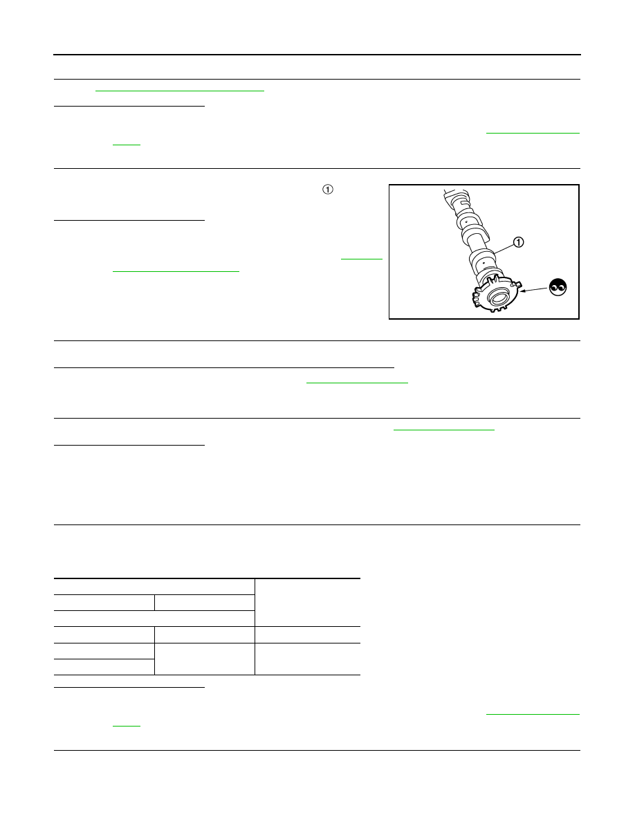
CHECK CAMSHAFT (EXH)

Check the following.
• Accumulation of debris to the signal plate of camshaft 

 rear end

• Chipping signal plate of camshaft front end
Is the inspection result normal?

YES

>> GO TO 7.

NO

>> Remove debris and clean the signal plate of camshaft

front end or replace camshaft. Refer to 

EM-197,

"Removal and Installation"

.

7.

CHECK TIMING CHAIN INSTALLATION

Check service records for any recent repairs that may cause timing chain misaligned.

Are there any service records that may cause timing chain misaligned?

YES

>> Check timing chain installation. Refer to 

EM-194, "Inspection"

.

NO

>> GO TO 8.

8.

CHECK LUBRICATION CIRCUIT

Perform “Inspection of Camshaft Sprocket (EXT) Oil Groove”. Refer to 

EM-200, "Inspection"

.

Is the inspection result normal?

YES

>> INSPECTION END

NO

>> Clean lubrication line.

Component Inspection

INFOID:0000000010702890

1.

CHECK EXHAUST VALVE TIMING CONTROL SOLENOID VALVE-1

1.

Turn ignition switch OFF.

2.

Disconnect exhaust valve timing control solenoid valve harness connector.

3.

Check resistance between exhaust valve timing control solenoid valve terminals as per the following.

Is the inspection result normal?

YES

>> GO TO 2.

NO

>> Replace malfunctioning exhaust valve timing control solenoid valve. Refer to 

EM-183, "Exploded

View"

.

2.

CHECK EXHAUST VALVE TIMING CONTROL SOLENOID VALVE-2

1.

Remove exhaust valve timing control solenoid valve.

PBIA9557J

Exhaust valve timing control solenoid valve

Resistance

+

Terminal

1

2

6.7  -7.7 

 (at 20

°

C)

1

Ground

Not exist

2

P0014 EVT CONTROL

ECM-163

< DTC/CIRCUIT DIAGNOSIS >

[MR20DD]

C

D

E

F

G

H

I

J

K

L

M

A

ECM

N

P

O

2.

Provide battery voltage between exhaust valve timing control
solenoid valve terminals 1 and 2, and then interrupt it. Check
that the plunger moves as shown in the figure. 

CAUTION:

Do not apply battery voltage continuously for 5 seconds or
more. Doing so may result in damage to the coil in exhaust
valve timing control solenoid valve.
NOTE:
Always replace O-ring when exhaust valve timing control sole-
noid valve is removed.

Is the inspection result normal?

YES

>> INSPECTION END

NO

>> Replace malfunctioning exhaust valve timing control solenoid valve. Refer to 

EM-183, "Exploded

View"

.

JMBIA0097ZZ

ECM-164

< DTC/CIRCUIT DIAGNOSIS >

[MR20DD]

P0031, P0032 A/F SENSOR 1 HEATER

P0031, P0032 A/F SENSOR 1 HEATER

DTC Description

INFOID:0000000010702891

DTC DETECTION LOGIC

POSSIBLE CAUSE

P0031

• Harness or connectors (The A/F sensor 1 heater circuit is open or shorted.)
• The A/F sensor 1 heater

P0032

• Harness or connectors (The A/F sensor 1 heater circuit is shorted.)
• The A/F sensor 1 heater

FAIL-SAFE

Not applicable

DTC CONFIRMATION PROCEDURE

1.

PRECONDITIONING

If DTC Confirmation Procedure has been previously conducted, always turn ignition switch OFF and wait at
least 10 seconds before conducting the next test.
TESTING CONDITION:
Before performing the following procedure, confirm that battery voltage is 11 V or more at idle.

>> GO TO 2.

2.

PERFORM DTC CONFIRMATION PROCEDURE

1.

Start engine and let it idle for at least 10 seconds.

2.

Check 1st trip DTC.

Is 1st trip DTC detected?

YES

>> Proceed to 

ECM-164, "Diagnosis Procedure"

.

NO-1

>> To check malfunction symptom before repair: Refer to 

GI-41, "Intermittent Incident"

.

NO-2

>> Confirmation after repair: INSPECTION END

Diagnosis Procedure

INFOID:0000000010702892

1.

CHECK AIR FUEL RATIO (A/F) SENSOR 1 POWER SUPPLY CIRCUIT

1.

Turn ignition switch OFF.

2.

Disconnect air fuel ratio (A/F) sensor 1 harness connector.

3.

Turn ignition switch ON.

4.

Check the voltage between A/F sensor 1 harness connector and ground.

DTC No.

CONSULT screen terms

(Trouble diagnosis content)

DTC detecting condition

P0031

A/F SEN1 HTR (B1)
(HO2S heater control circuit low bank 1 
sensor 1)

An excessively low voltage signal is sent to ECM through the A/F sensor 1 
heater.

P0032

A/F SEN1 HTR (B1)
(HO2S heater control circuit high bank 1 
sensor 1)

An excessively high voltage signal is sent to ECM through the A/F sensor 
1 heater.

+

Ground

Voltage

A/F sensor 1

Connector Terminal

F74

4

Ground

Battery voltage

P0031, P0032 A/F SENSOR 1 HEATER

ECM-165

< DTC/CIRCUIT DIAGNOSIS >

[MR20DD]

C

D

E

F

G

H

I

J

K

L

M

A

ECM

N

P

O

Is the inspection result normal?

YES

>> GO TO 2.

NO

>> Repair or replace malfunctioning part.

2.

CHECK A/F SENSOR 1 HEATER OUTPUT SIGNAL CIRCUIT FOR OPEN AND SHORT

1.

Turn ignition switch OFF.

2.

Disconnect ECM harness connector.

3.

Check the continuity between A/F sensor 1 harness connector and ECM harness connector.

4.

Also check harness for short to ground and short to power.

Is the inspection result normal?

YES

>> GO TO 3.

NO

>> Repair or replace malfunctioning part.

3.

CHECK A/F SENSOR 1 HEATER

Refer to 

ECM-165, "Component Inspection"

.

Is the inspection result normal?

YES

>> INSPECTION END

NO

>> GO TO 4.

4.

REPLACE A/F SENSOR 1

Replace malfunctioning A/F sensor 1. Refer to 

EM-153, "Exploded View"

.

CAUTION:

• Discard any A/F sensor which has been dropped from a height of more than 0.5 m (19.7 in) onto a

hard surface such as a concrete floor; use a new one.

• Before installing new A/F sensor, clean exhaust system threads.

>> INSPECTION END

Component Inspection

INFOID:0000000010702893

1.

CHECK AIR FUEL RATIO (A/F) SENSOR 1 HEATER

1.

Turn ignition switch OFF.

2.

Disconnect air fuel ratio (A/F) sensor 1 harness connector.

3.

Check resistance between A/F sensor 1 terminals as per the following.

Is the inspection result normal?

YES

>> INSPECTION END

NO

>> GO TO 2.

2.

REPLACE A/F SENSOR 1

+

Continuity

A/F sensor 1

ECM

Connector Terminal

Connector Terminal

F74

3

F16

93

Existed

A/F sensor 1

Resistance

+

Terminal

3

4

1.80 - 2.44 

 [at 25

°

(77

°

F)]

1

Not exist

2

4

1

2

ECM-166

< DTC/CIRCUIT DIAGNOSIS >

[MR20DD]

P0031, P0032 A/F SENSOR 1 HEATER

Replace malfunctioning A/F sensor 1. Refer to 

EM-153, "Exploded View"

.

CAUTION:

• Discard any A/F sensor which has been dropped from a height of more than 0.5 m (19.7 in) onto a

hard surface such as a concrete floor; use a new one.

• Before installing new A/F sensor, clean exhaust system threads.

>> INSPECTION END

P0037, P0038 HO2S2 HEATER

ECM-167

< DTC/CIRCUIT DIAGNOSIS >

[MR20DD]

C

D

E

F

G

H

I

J

K

L

M

A

ECM

N

P

O

P0037, P0038 HO2S2 HEATER

DTC Description

INFOID:0000000010702894

DTC DETECTION LOGIC

POSSIBLE CAUSE

P0037

• Harness or connectors (The heated oxygen sensor 2 heater circuit is open or shorted.)
• Heated oxygen sensor 2 heater

P0038

• Harness or connectors (The heated oxygen sensor 2 heater circuit is shorted.)
• Heated oxygen sensor 2 heater

FAIL-SAFE

Not applicable

DTC CONFIRMATION PROCEDURE

1.

PRECONDITIONING

If DTC Confirmation Procedure has been previously conducted, always turn ignition switch OFF and wait at
least 10 seconds before conducting the next test.
TESTING CONDITION:
Before performing the following procedure, confirm that battery voltage is between 11 to 16 V at idle.

>> GO TO 2.

2.

PERFORM DTC CONFIRMATION PROCEDURE

1.

Start engine and warm it up to the normal operating temperature.

2.

Turn ignition switch OFF and wait at least 10 seconds.

3.

Start engine and keep the engine speed between 3,500 and 4,000 rpm for at least 1 minute under no load.

4.

Let engine idle for 1 minute.

5.

Check 1st trip DTC.

Is 1st trip DTC detected?

YES

>> Proceed to 

ECM-167, "Diagnosis Procedure"

.

NO-1

>> To check malfunction symptom before repair: Refer to 

GI-41, "Intermittent Incident"

.

NO-2

>> Confirmation after repair: INSPECTION END

Diagnosis Procedure

INFOID:0000000010702895

1.

CHECK HEATED OXYGEN SENSOR 2 (HO2S2) POWER SUPPLY CIRCUIT

1.

Turn ignition switch OFF.

2.

Disconnect heated oxygen sensor 2 (HO2S2) harness connector.

3.

Turn ignition switch ON.

4.

Check the voltage between HO2S2 harness connector and ground.

DTC No.

CONSULT screen terms

(Trouble diagnosis content)

DTC detecting condition

P0037

HO2S2 HTR (B1)
(HO2S heater control circuit low bank 1 
sensor 2)

An excessively low voltage signal is sent to ECM through the heated oxy-
gen sensor 2 heater.

P0038

HO2S2 HTR (B1)
(HO2S heater control circuit high bank 1 
sensor 2)

An excessively high voltage signal is sent to ECM through the heated oxy-
gen sensor 2 heater.

ECM-168

< DTC/CIRCUIT DIAGNOSIS >

[MR20DD]

P0037, P0038 HO2S2 HEATER

Is the inspection result normal?

YES

>> GO TO 2.

NO

>> Repair or replace malfunctioning part.

2.

CHECK HO2S2 HEATER OUTPUT SIGNAL CIRCUIT FOR OPEN AND SHORT

1.

Turn ignition switch OFF.

2.

Disconnect ECM harness connector.

3.

Check the continuity between HO2S2 harness connector and ECM harness connector.

4.

Also check harness for short to ground and short to power.

Is the inspection result normal?

YES

>> GO TO 3.

NO

>> Repair or replace malfunctioning part.

3.

CHECK HO2S2 HEATER

Refer to 

ECM-168, "Component Inspection"

.

Is the inspection result normal?

YES

>> INSPECTION END

NO

>> GO TO 4.

4.

REPLACE HEATED OXYGEN SENSOR 2

Replace malfunctioning heated oxygen sensor 2. Refer to 

EX-11, "Exploded View"

.

CAUTION:

• Discard any heated oxygen sensor which has been dropped from a height of more than 0.5 m

(19.7in) onto a hard surface such as a concrete floor; use a new one.

• Before installing new oxygen sensor, clean exhaust system threads.

>> INSPECTION END

Component Inspection

INFOID:0000000010702896

1.

CHECK HEATED OXYGEN SENSOR 2 HEATER

1.

Turn ignition switch OFF.

2.

Disconnect heated oxygen sensor 2 (HO2S2) harness connector.

3.

Check resistance between HO2S2 terminals as follows.

+

Ground

Voltage

HO2S2

Connector Terminal

F35

4

Ground

Battery voltage

+

Continuity

HO2S2

ECM

Connector

Terminal

Connector

Terminal

F35

3

F16

89

Existed

HO2S2

Resistance

+

Terminal

4

3

3.4 - 4.4 

 [at 25

°

(77

°

F)]

P0037, P0038 HO2S2 HEATER

ECM-169

< DTC/CIRCUIT DIAGNOSIS >

[MR20DD]

C

D

E

F

G

H

I

J

K

L

M

A

ECM

N

P

O

Is the inspection result normal?

YES

>> INSPECTION END

NO

>> GO TO 2.

2.

REPLACE HEATED OXYGEN SENSOR 2

Replace malfunctioning heated oxygen sensor 2. Refer to 

EX-11, "Exploded View"

.

CAUTION:

• Discard any heated oxygen sensor which has been dropped from a height of more than 0.5 m (19.7

in) onto a hard surface such as a concrete floor; use a new one.

• Before installing new oxygen sensor, clean exhaust system threads.

>> INSPECTION END

1

2

Not exist

3

4

4

1

2

3

HO2S2

Resistance

+

Terminal

ECM-170

< DTC/CIRCUIT DIAGNOSIS >

[MR20DD]

P0075 IVT CONTROL SOLENOID VALVE

P0075 IVT CONTROL SOLENOID VALVE

DTC Description

INFOID:0000000010702897

DTC DETECTION LOGIC

POSSIBLE CAUSE

• Harness or connectors (Intake valve timing control solenoid valve circuit is open or shorted.)
• Intake valve timing control solenoid valve

FAIL-SAFE

DTC CONFIRMATION PROCEDURE

1.

PRECONDITIONING

If DTC Confirmation Procedure has been previously conducted, always turn ignition switch OFF and wait at
least 10 seconds before conducting the next test.

>> GO TO 2.

2.

PERFORM DTC CONFIRMATION PROCEDURE

1.

Start engine and let it idle for 5 seconds.

2.

Check 1st trip DTC.

Is 1st trip DTC detected?

YES

>> Proceed to 

ECM-170, "Diagnosis Procedure"

.

NO-1

>> To check malfunction symptom before repair: Refer to 

GI-41, "Intermittent Incident"

.

NO-2

>> Confirmation after repair: INSPECTION END

Diagnosis Procedure

INFOID:0000000010702898

1.

CHECK INTAKE VALVE TIMING CONTROL SOLENOID VALVE POWER SUPPLY CIRCUIT-1

1.

Turn ignition switch OFF.

2.

Disconnect intake valve timing (IVT) control solenoid valve harness connector.

3.

Turn ignition switch ON.

4.

Check the voltage between IVT control solenoid valve harness connector and ground.

Is the inspection result normal?

YES

>> GO TO 3.

NO

>> GO TO 2.

2.

CHECK INTAKE VALVE TIMING CONTROL SOLENOID VALVE POWER SUPPLY CIRCUIT-2

DTC No.

CONSULT screen terms

(Trouble diagnosis content)

DTC detecting condition

P0075

INT/V TIM V/CIR-B1
(Intake valve control solenoid circuit bank 1)

An improper voltage is sent to the ECM through intake valve timing control 
solenoid valve.

Engine operating condition in fail-safe mode

Fail safe mode

Vehicle behavior

Device fix mode

• This mode fixes the IVT control solenoid valve and the EVT control solenoid valve in the refer-

ence position.

• The intake manifold runner control valve motor is turned OFF (intake manifold runner control 

valve opens).

+

Ground

Voltage

IVT control solenoid valve

Connector

Terminal

F94

1

Ground

Battery voltage

P0075 IVT CONTROL SOLENOID VALVE

ECM-171

< DTC/CIRCUIT DIAGNOSIS >

[MR20DD]

C

D

E

F

G

H

I

J

K

L

M

A

ECM

N

P

O

1.

Turn ignition switch OFF.

2.

Disconnect IPDM E/R harness connector.

3.

Check the continuity between IVT control solenoid valve harness connector and IPDM E/R harness con-
nector.

4.

Also check harness for short to ground and short to power.

Is the inspection result normal?

YES

>> GO TO 4.

NO

>> Repair or replace malfunctioning part.

3.

CHECK IVT CONTROL SOLENOID VALVE OUTPUT SIGNAL CIRCUIT FOR OPEN AND SHORT

1.

Turn ignition switch OFF.

2.

Disconnect ECM harness connector.

3.

Check the continuity between IVT control solenoid valve harness connector and ECM harness connector.

4.

Also check harness for short to ground and short to power.

Is the inspection result normal?

YES

>> GO TO 4.

NO

>> Repair or replace malfunctioning part.

4.

CHECK IVT CONTROL SOLENOID VALVE

Refer to 

ECM-158, "Component Inspection"

Is the inspection result normal?

YES

>> INSPECTION END

NO

>> Replace malfunctioning IVT control solenoid valve. Refer to 

EM-183, "Exploded View"

.

Component Inspection

INFOID:0000000010702899

1.

CHECK INTAKE VALVE TIMING CONTROL SOLENOID VALVE-1

1.

Turn ignition switch OFF.

2.

Disconnect intake valve timing control solenoid valve harness connector.

3.

Check resistance between intake valve timing control solenoid valve terminals as per the following.

Is the inspection result normal?

YES

>> GO TO 2.

NO

>> Replace malfunctioning intake valve timing control solenoid valve. Refer to 

EM-183, "Exploded

View"

.

+

Continuity

IVT control solenoid valve

IPDM E/R

Connector

Terminal

Connector

Terminal

F94

1

F90

96

Existed

+

Continuity

IVT control solenoid valve

ECM

Connector

Terminal

Connector

Terminal

F94

2

F16

94

Existed

IVT control solenoid valve

Resistance

+

Terminal

1

2

6.7 - 7.7 

 [at 20

°

(68

°

F)]

1

Ground

Not exist

2

ECM-172

< DTC/CIRCUIT DIAGNOSIS >

[MR20DD]

P0075 IVT CONTROL SOLENOID VALVE

2.

CHECK INTAKE VALVE TIMING CONTROL SOLENOID VALVE-2

1.

Remove intake valve timing control solenoid valve.

2.

Provide battery voltage between intake valve timing control sole-
noid valve terminals 1 and 2, and then interrupt it. Check that the
plunger moves as shown in the figure. 

CAUTION:

Never apply battery voltage continuously for 5 seconds or
more. Doing so may result in damage to the coil in intake
valve timing control solenoid valve.
NOTE:
Always replace O-ring when intake valve timing control solenoid
valve is removed.

Is the inspection result normal?

YES

>> INSPECTION END

NO

>> Replace malfunctioning intake valve timing control solenoid valve. Refer to 

EM-183, "Exploded

View"

.

JMBIA0097ZZ

P0078 EVT CONTROL SOLENOID VALVE

ECM-173

< DTC/CIRCUIT DIAGNOSIS >

[MR20DD]

C

D

E

F

G

H

I

J

K

L

M

A

ECM

N

P

O

P0078 EVT CONTROL SOLENOID VALVE

DTC Description

INFOID:0000000010702900

DTC DETECTION LOGIC

POSSIBLE CAUSE

• Harness or connectors
- Exhaust valve timing control solenoid valve circuit is open or shorted.
- Sensor power supply circuit 2 is shorted.
• Exhaust valve timing control solenoid valve
• Sensor power supply circuit 2 sensor

FAIL-SAFE

DTC CONFIRMATION PROCEDURE

1.

PRECONDITIONING

If DTC Confirmation Procedure has been previously conducted, always turn ignition switch OFF and wait at
least 10 seconds before conducting the next test.

>> GO TO 2.

2.

PERFORM DTC CONFIRMATION PROCEDURE

1.

Start engine and let it idle for at least 5 seconds.

2.

Check 1st trip DTC.

Is 1st trip DTC detected?

YES

>> Proceed to 

ECM-173, "Diagnosis Procedure"

.

NO-1

>> To check malfunction symptom before repair: Refer to 

GI-41, "Intermittent Incident"

.

NO-2

>> Confirmation after repair: INSPECTION END

Diagnosis Procedure

INFOID:0000000010702901

1.

CHECK EXHAUST VALVE TIMING CONTROL SOLENOID VALVE POWER SUPPLY

1.

Turn ignition switch OFF.

2.

Disconnect exhaust valve timing (EVT) control solenoid valve harness connector.

3.

Turn ignition switch ON.

4.

Check the voltage between EVT control solenoid valve harness connector and ground.

Is the inspection result normal?

DTC No.

CONSULT screen terms

(Trouble diagnosis content)

DTC detecting condition

P0078

EX V/T ACT/CIRC-B1
(Exhaust valve control solenoid circuit bank 
1)

An improper voltage is sent to the ECM through exhaust valve timing con-
trol solenoid valve.

Engine operating condition in fail-safe mode

Fail safe mode

Vehicle behavior

Device fix mode

• This mode fixes the IVT control solenoid valve and the EVT control solenoid valve in the refer-

ence position.

• The intake manifold runner control valve motor is turned OFF (intake manifold runner control 

valve opens).

+

Ground

Voltage

EVT control solenoid valve

Connector

Terminal

F78

1

Ground

Battery voltage

ECM-174

< DTC/CIRCUIT DIAGNOSIS >

[MR20DD]

P0078 EVT CONTROL SOLENOID VALVE

YES

>> GO TO 3.

NO

>> GO TO 2.

2.

CHECK EXHAUST VALVE TIMING CONTROL SOLENOID VALVE POWER SUPPLY CIRCUIT

1.

Turn ignition switch OFF.

2.

Disconnect IPDM E/R harness connector.

3.

Check the continuity between EVT control solenoid valve harness connector and IPDM E/R harness con-
nector.

4.

Also check harness for short to ground and short to power.

Is the inspection result normal?

YES

>> Perform trouble diagnosis for the power supply circuit.

NO

>> Repair or replace malfunctioning part.

3.

CHECK EVT CONTROL SOLENOID VALVE OUTPUT SIGNAL CIRCUIT FOR OPEN AND SHORT

1.

Turn ignition switch OFF.

2.

Disconnect ECM harness connector.

3.

Check the continuity between EVT control solenoid valve harness connector and ECM harness connec-
tor.

4.

Also check harness for short to ground and short to power.

Is the inspection result normal?

YES

>> GO TO 4.

NO

>> Repair or replace malfunctioning part.

4.

CHECK EVT CONTROL SOLENOID VALVE

Refer to 

ECM-174, "Component Inspection"

.

Is the inspection result normal?

YES

>> INSPECTION END

NO

>> Replace malfunctioning EVT control solenoid valve. Refer to 

EM-183, "Exploded View"

.

Component Inspection

INFOID:0000000010702902

1.

CHECK EXHAUST VALVE TIMING CONTROL SOLENOID VALVE-1

1.

Turn ignition switch OFF.

2.

Disconnect exhaust valve timing control solenoid valve harness connector.

3.

Check resistance between exhaust valve timing control solenoid valve terminals as per the following.

+

Continuity

EVT control solenoid valve

IPDM E/R

Connector

Terminal

Connector

Terminal

F78

1

F90

96

Existed

+

Continuity

EVT control solenoid valve

ECM

Connector

Terminal

Connector

Terminal

F78

2

F16

95

Existed

EVT control solenoid valve

Resistance

+

Terminal

1

2

6.7 -7.7 

 [at 20

°

(68

°

F)]

1

Ground

Not exist.

2

P0078 EVT CONTROL SOLENOID VALVE

ECM-175

< DTC/CIRCUIT DIAGNOSIS >

[MR20DD]

C

D

E

F

G

H

I

J

K

L

M

A

ECM

N

P

O

Is the inspection result normal?

YES

>> GO TO 2.

NO

>> Replace malfunctioning exhaust valve timing control solenoid valve. Refer to 

EM-183, "Exploded

View"

.

2.

CHECK EXHAUST VALVE TIMING CONTROL SOLENOID VALVE-2

1.

Remove exhaust valve timing control solenoid valve.

2.

Provide battery voltage between exhaust valve timing control
solenoid valve terminals 1 and 2, and then interrupt it. Check
that the plunger moves as shown in the figure.

CAUTION:

Do not apply battery voltage continuously for 5 seconds or
more. Doing so may result in damage to the coil in exhaust
valve timing control solenoid valve.
NOTE:
Always replace O-ring when exhaust valve timing control sole-
noid valve is removed.

Is the inspection result normal?

YES

>> INSPECTION END

NO

>> Replace exhaust valve timing control solenoid valve. Refer to 

EM-183, "Exploded View"

.

JMBIA0097ZZ

ECM-176

< DTC/CIRCUIT DIAGNOSIS >

[MR20DD]

P0087, P0088, P0090 FRP CONTROL SYSTEM

P0087, P0088, P0090 FRP CONTROL SYSTEM

DTC Description

INFOID:0000000010702903

DTC DETECTION LOGIC

NOTE:
DTC P0087, P0088 or P0090 may be displayed when running out of gas.

POSSIBLE CAUSE

• Harness or connectors
- The high pressure fuel pump circuit is open or shorted.
- The low pressure fuel pump circuit is open or shorted.
• High pressure fuel pump
• High pressure fuel pump system
• Low  pressure fuel pump
• Low  pressure fuel pump system
• Fuel pressure regulator
• Fuel rail pressure sensor
• Incorrect hose connection
• Out of gas

FAIL-SAFE

DTC CONFIRMATION PROCEDURE

1.

CHECK DTC PRIORITY

If DTC P0087, P0088 or P0090 is displayed with DTC P1197, first perform the trouble diagnosis for DTC
P1197.

Is applicable DTC detected?

YES

>> Perform diagnosis of applicable. Refer to 

ECM-317, "DTC Description"

.

NO

>> GO TO 2.

2.

PRECONDITIONING

If DTC Confirmation Procedure has been previously conducted, always turn ignition switch OFF and wait at
least 10 seconds before conducting the next test.
TESTING CONDITION:
Before performing the following procedure, confirm that battery voltage is 11 V or more at idle.

DTC No.

CONSULT screen terms

(Trouble diagnosis content)

DTC detecting condition

P0087

LOW FUEL PRES

The following condition continues for 5 seconds or more after engine start.
• Target fuel pressure

 Actual fuel pressure > 2.7 MPa

P0088

HIGH FUEL PRES

The following condition continues for 5 seconds or more after engine start.
• Actual fuel pressure 

 Target fuel pressure > 2.7 MPa

P0090

FUEL PRESSURE CONTROL FUNCTION

The following condition continues for 5 seconds or more after engine start.
• Fuel rail pressure remains at 1.1 MPa or less. 
• Fuel rail pressure remains at 18.5 MPa or more.

Engine operating condition in fail-safe mode

Fail safe mode

Vehicle behavior

Traveling con-
trol mode

Accelerator an-
gle variation 
control

ECM controls the accelerator pedal depression speed to make it slower than actual speed. This 
causes a drop in accelerating performance and encourages the driver to repair malfunction.
NOTE:
ECM does not control the accelerator pedal releasing speed.

Combustion 
control mode

Stratified charge 
combustion 
control at start-
ing

No stratified charge combustion at starting (cold start).

P0087, P0088, P0090 FRP CONTROL SYSTEM

ECM-177

< DTC/CIRCUIT DIAGNOSIS >

[MR20DD]

C

D

E

F

G

H

I

J

K

L

M

A

ECM

N

P

O

>> GO TO 3.

3.

DTC CONFIRMATION PROCEDURE-1

1.

Check that the fuel tank is 1/8 full of fuel.

2.

Warm up the engine to the normal operating temperature and keep the engine speed at idle for 15 sec-
onds.
NOTE:
Warm up the engine until “COOLAN TEMP/S” on “DATA MONITOR” of CONSULT reaches at least 70

°

C

(158

°

F).

3.

Check 1st trip DTC.

Is 1st trip DTC detected?

YES

>> Proceed to 

ECM-173, "Diagnosis Procedure"

.

NO

>> GO TO 4.

4.

DTC CONFIRMATION PROCEDURE-2

1.

Cool the engine until the engine coolant temperature reaches 60

°

C (140

°

F) or less.

2.

Start the engine and wait at least 40 seconds.

3.

Check 1st trip DTC.

Is 1st trip DTC detected?

YES

>> Proceed to 

ECM-173, "Diagnosis Procedure"

.

NO-1

>> To check malfunction symptom before repair: Refer to 

GI-41, "Intermittent Incident"

.

NO-2

>> Confirmation after repair: INSPECTION END

Diagnosis Procedure

INFOID:0000000010702904

1.

CHECK DTC PRIORITY

If DTC P0087, P0088 or P0090 is displayed with DTC P1197, first perform the trouble diagnosis for DTC
P1197.

Is applicable DTC detected?

YES

>> Perform diagnosis of applicable. Refer to 

ECM-317, "DTC Description"

.

NO

>> GO TO 2.

2.

CHECK HIGH PRESSURE FUEL PUMP

Refer to 

ECM-177, "Component Inspection"

.

Is the inspection result normal?

YES

>> GO TO 3.

NO

>> Replace high pressure fuel pump. Refer to 

EM-159, "Removal and Installation"

.

3.

CHECK FUEL LEAKAGE

1.

Start the engine.

2.

Visually check that the fuel pump, fuel rail, and fuel piping have no fuel leakage.

Is the inspection result normal?

YES

>> INSPECTION END

NO

>> Repair or replace malfunctioning part.

Component Inspection

INFOID:0000000010702905

1.

CHECK HIGH PRESSURE FUEL PUMP-1

1.

Turn ignition switch OFF.

2.

Disconnect high pressure fuel pump harness connector.

3.

Check the resistance between high pressure fuel pump terminals as follows.


Content      ..     9      10      11      12     ..