Qashqai J11. Engine control system (K9K) - part 25


  Index      Nissan     Qashqai J11. Engine control system (K9K). Service and Repair Manual


Search            copyright infringement  


Content      ..     23      24      25      26     ..


Qashqai J11. Engine control system (K9K) - part 25


STOP/START OFF SWITCH

ECK-385

< DTC/CIRCUIT DIAGNOSIS >

[K9K]

C

D

E

F

G

H

I

J

K

L

M

A

ECK

N

P

O

Is the inspection result normal?

YES

>> GO TO 5.

NO

>> GO TO 4.

4.

CHECK STOP/START OFF SWITCH INPUT SIGNAL CIRCUIT

1.

Disconnect BCM harness connector.

2.

Check the continuity between BCM harness connector and stop/start OFF switch harness connector.

3.

Also check harness for short to ground and short to power.

Is the inspection result normal?

YES

>> Check BCM power supply and ground circuit.

NO

>> Repair or replace error-detected parts.

5.

CHECK STOP/START OFF SWITCH GROUND CIRCUIT

1.

Turn ignition switch OFF.

2.

Check the continuity between stop/start OFF switch harness connector and ground.

3.

Also check harness for short to ground and to power.

Is the inspection result normal?

YES

>> GO TO 6.

NO

>> Repair or replace error-detected parts.

6.

CHECK STOP/START OFF SWITCH

Check the stop/start OFF switch. Refer to 

ECK-386, "Component Inspection"

.

Is the inspection result normal?

YES

>> INSPECTION END

NO

>> Replace stop/start OFF switch.

Component Inspection

INFOID:0000000010434293

1.

CHECK STOP/START OFF SWITCH

1.

Turn ignition switch OFF.

2.

Disconnect stop/start OFF switch harness connector.

3.

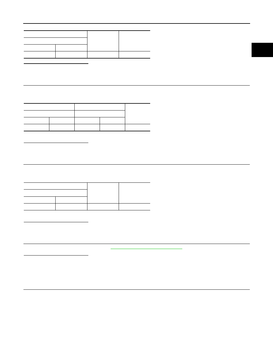
Check the continuity between stop/start OFF switch harness connectors as per the following condition.

+

Voltage

(Approx.)

Stop/start OFF switch

Connector

Terminal

M110

1

Ground

Battery voltage

+

Continuity

BCM

Stop/start OFF switch

Connector

Terminal

Connector

Terminal

M69

99

M110

1

Existed

Continuity

Stop/start OFF switch

Connector

Terminal

M110

2

Ground

Existed

ECK-386

< DTC/CIRCUIT DIAGNOSIS >

[K9K]

STOP/START OFF SWITCH

Is the inspection result normal?

YES

>> INSPECTION END

NO

>> Replace stop/start OFF switch.

Stop/start OFF switch

Condition

Continuity

+

Terminal

1

2

Stop/start OFF switch

Pressed

Existed

Released

Not existed

ENGINE CONTROL SYSTEM SYMPTOMS

ECK-387

< SYMPTOM DIAGNOSIS >

[K9K]

C

D

E

F

G

H

I

J

K

L

M

A

ECK

N

P

O

SYMPTOM DIAGNOSIS

ENGINE CONTROL SYSTEM SYMPTOMS

Symptom Table

INFOID:0000000010290070

SYSTEM — Basic engine control system

SYMPTOM

Reference 
page

HARD/NO ST

AR

T

/REST

AR

T

 (EXCP

. HA

)

ENGINE ST

ALL

HES

IT

A

TION/SURGING/FLA

T

 SPOT

KN

OCK/D

E

T

O

NA

TION

LACK OF

 POWER

P

O

OR ACCELERA

TION

HI

 IDLE

LOW I

D

LE

NO ST

AR

T (with f

irst firing)

NO ST

AR

T (without 

first f

iring)

HARD T

O

 ST

AR

T WHEN 

ENGINE IS 

CO

LD

HARD T

O

 ST

AR

T WHEN 

ENGINE IS 

HO

T

AT

 I

D

L

E

DURING DRIV

ING

WHEN DECELE

R

A

TING

Warranty symptom code

AA

AB

AC

AD

AE

AF

Engine  body

x

x

x

x

x

x

x

x

x

x

x

EM-318, 

"Exploded 

View"

Air cleaner and duct

x

x

EM-279, 

"Exploded 

View"

ECM

x

x

x

x

x

x

x

x

x

x

x

x

x

ECK-268, 

"DTC Log-

ic"

ECK-269, 

"DTC Log-

ic"

ECK-270, 

"DTC Log-

ic"

 , 

ECK-271, 

"DTC Log-

ic"

,

ECK-274, 

"DTC Log-

ic"

ECK-388

< SYMPTOM DIAGNOSIS >

[K9K]

ENGINE CONTROL SYSTEM SYMPTOMS

Camshaft position sensor circuit

x

x

ECK-231, 

"DTC Log-

ic"

Crankshaft  position  sensor  circuit

x

x

x

x

x

x

x

x

x

x

ECK-229, 

"DTC Log-

ic"

Mass air flow sensor circuit

x

x

x

ECK-193, 

"DTC Log-

ic"

,

Intake air temperature sensor 1 circuit

ECK-199, 

"DTC Log-

ic"

,

ECK-199, 

"DTC Log-

ic"

Turbocharger boost sensor circuit

x

x

x

ECK-197, 

"DTC Log-

ic"

Intake air temperature sensor 2 circuit

ECK-190, 

"DTC Log-

ic"

Engine coolant temperature sensor circuit

x

x

x

x

ECK-201, 

"DTC Log-

ic"

Fuel  injector  circuit

x

x

x

x

x

x

x

x

x

x

x

x

x

ECK-211, 

"DTC Log-

ic"

SYSTEM — Basic engine control system

SYMPTOM

Reference 
page

HARD/NO ST

AR

T

/REST

AR

T

 (EXCP

. HA)

ENGINE ST

ALL

HESI

T

A

TI

ON

/S

URGI

N

G/

FLA

T

 SPOT

KNOCK/DET

O

NA

TION

LACK OF

 PO

WER

POOR ACCELERA

TION

HI IDLE

LOW I

D

LE

NO ST

AR

T (wit

h f

irst firing)

NO ST

AR

T (wit

ho

ut 

first fi

rin

g

)

HARD T

O

 ST

AR

T WHEN 

ENGI

NE IS 

C

O

LD

HARD T

O

 ST

AR

T WHEN 

ENGI

NE IS 

H

O

T

AT

 I

D

L

E

DURING DRIVING

WH

E

N

 DECELERA

TIN

G

Warranty symptom code

AA

AB

AC

AD

AE

AF

ENGINE CONTROL SYSTEM SYMPTOMS

ECK-389

< SYMPTOM DIAGNOSIS >

[K9K]

C

D

E

F

G

H

I

J

K

L

M

A

ECK

N

P

O

High  pressure  fuel  pump

x

x

x

x

x

x

x

x

x

x

x

Fuel rail pressure sensor circuit

x

ECK-209, 

"DTC Log-

ic"

Fuel temperature sensor circuit

ECK-205, 

"DTC Log-

ic"

Fuel pressure sensor

Fuel  pump

x

x

x

x

x

x

x

x

x

x

x

Fuel heater circuit

Turbocharger boost control solenoid valve cir-
cuit

x

x

x

ECK-183, 

"DTC Log-

ic"

EGR volume control valve circuit

x

x

x

ECK-235, 

"DTC Log-

ic"

ECK-

238, "DTC 

Logic"

SYSTEM — Basic engine control system

SYMPTOM

Reference 
page

HARD/NO ST

AR

T

/REST

AR

T

 (EXCP

. HA)

ENGINE ST

ALL

HESI

T

A

TI

ON

/S

URGI

N

G/

FLA

T

 SPOT

KNOCK/DET

O

NA

TION

LACK OF

 PO

WER

POOR ACCELERA

TION

HI IDLE

LOW I

D

LE

NO ST

AR

T (wit

h f

irst firing)

NO ST

AR

T (wit

ho

ut 

first fi

rin

g

)

HARD T

O

 ST

AR

T WHEN 

ENGI

NE IS 

C

O

LD

HARD T

O

 ST

AR

T WHEN 

ENGI

NE IS 

H

O

T

AT

 I

D

L

E

DURING DRIVING

WH

E

N

 DECELERA

TIN

G

Warranty symptom code

AA

AB

AC

AD

AE

AF

ECK-390

< SYMPTOM DIAGNOSIS >

[K9K]

ENGINE CONTROL SYSTEM SYMPTOMS

Low pressure EGR volume control valve circuit

ECK-306, 

"DTC Log-

ic"

ECK-

308, "DTC 

Logic"

ECK-312, 

"DTC Log-

ic"

ECK-

314, "DTC 

Logic"

Electric  throttle  control  actuator  circuit

x

x

x

x

x

x

x

x

x

ECK-275, 

"DTC Log-

ic"

ECK-

364, "DTC 

Logic"

Exhaust electric throttle control actuator circuit

x

ECK-296, 

"DTC Log-

ic"

ECK-

299, "DTC 

Logic"

ECK-302, 

"DTC Log-

ic"

ECK-

304, "DTC 

Logic"

DPF (Diesel Particulate Filter)

ECK-359, 

"DTC Log-

ic"

SYSTEM — Basic engine control system

SYMPTOM

Reference 
page

HARD/NO ST

AR

T

/REST

AR

T

 (EXCP

. HA)

ENGINE ST

ALL

HESI

T

A

TI

ON

/S

URGI

N

G/

FLA

T

 SPOT

KNOCK/DET

O

NA

TION

LACK OF

 PO

WER

POOR ACCELERA

TION

HI IDLE

LOW I

D

LE

NO ST

AR

T (wit

h f

irst firing)

NO ST

AR

T (wit

ho

ut 

first fi

rin

g

)

HARD T

O

 ST

AR

T WHEN 

ENGI

NE IS 

C

O

LD

HARD T

O

 ST

AR

T WHEN 

ENGI

NE IS 

H

O

T

AT

 I

D

L

E

DURING DRIVING

WH

E

N

 DECELERA

TIN

G

Warranty symptom code

AA

AB

AC

AD

AE

AF

ENGINE CONTROL SYSTEM SYMPTOMS

ECK-391

< SYMPTOM DIAGNOSIS >

[K9K]

C

D

E

F

G

H

I

J

K

L

M

A

ECK

N

P

O

Exhaust gas pressure sensor circuit

ECK-243, 

"DTC Log-

ic"

ECK-

245, "DTC 

Logic"

DPF differential pressure sensor circuit

ECK-294, 

"DTC Log-

ic"

ECK-

372, "DTC 

Logic"

Exhaust gas temperature sensor 1 circuit

ECK-259, 

"DTC Log-

ic"

,  

ECK-

327, "DTC 

Logic"

ECK-361, 

"DTC Log-

ic"

Exhaust gas temperature sensor 2 circuit

ECK-324, 

"DTC Log-

ic"

Glow control unit circuit

x

x

x

x

ECK-233, 

"DTC Log-

ic"

Glow plug circuit

x

x

x

x

ECK-233, 

"DTC Log-

ic"

Cooling fan resister circuit

x

x

SYSTEM — Basic engine control system

SYMPTOM

Reference 
page

HARD/NO ST

AR

T

/REST

AR

T

 (EXCP

. HA)

ENGINE ST

ALL

HESI

T

A

TI

ON

/S

URGI

N

G/

FLA

T

 SPOT

KNOCK/DET

O

NA

TION

LACK OF

 PO

WER

POOR ACCELERA

TION

HI IDLE

LOW I

D

LE

NO ST

AR

T (wit

h f

irst firing)

NO ST

AR

T (wit

ho

ut 

first fi

rin

g

)

HARD T

O

 ST

AR

T WHEN 

ENGI

NE IS 

C

O

LD

HARD T

O

 ST

AR

T WHEN 

ENGI

NE IS 

H

O

T

AT

 I

D

L

E

DURING DRIVING

WH

E

N

 DECELERA

TIN

G

Warranty symptom code

AA

AB

AC

AD

AE

AF

ECK-392

< SYMPTOM DIAGNOSIS >

[K9K]

ENGINE CONTROL SYSTEM SYMPTOMS

1 - 5: The numbers refer to the order of inspection.

(continued on next page)

Thermoplunger unit circuit

Thermoplunger control unit circuit

ECK-336, 

"DTC Log-

ic"

ECK-

339, "DTC 

Logic"

ECK-342, 

"DTC Log-

ic"

Accelerator pedal position sensor circuit

x

x

x

ECK-219, 

"DTC Log-

ic"

,

ECK-

221, "DTC 

Logic"

ECK-365, 

"DTC Log-

ic"

Refrigerant pressure sensor circuit

x

x

x

ECK-257, 

"DTC Log-

ic"

NATS (Nissan Anti-theft System)

x

SEC-77, 

"Work 

Flow"

SEC-231, 

"Work 

Flow"

SYSTEM — Basic engine control system

SYMPTOM

Reference 
page

HARD/NO ST

AR

T

/REST

AR

T

 (EXCP

. HA)

ENGINE ST

ALL

HESI

T

A

TI

ON

/S

URGI

N

G/

FLA

T

 SPOT

KNOCK/DET

O

NA

TION

LACK OF

 PO

WER

POOR ACCELERA

TION

HI IDLE

LOW I

D

LE

NO ST

AR

T (wit

h f

irst firing)

NO ST

AR

T (wit

ho

ut 

first fi

rin

g

)

HARD T

O

 ST

AR

T WHEN 

ENGI

NE IS 

C

O

LD

HARD T

O

 ST

AR

T WHEN 

ENGI

NE IS 

H

O

T

AT

 I

D

L

E

DURING DRIVING

WH

E

N

 DECELERA

TIN

G

Warranty symptom code

AA

AB

AC

AD

AE

AF

STOP/START SYSTEM

ECK-393

< SYMPTOM DIAGNOSIS >

[K9K]

C

D

E

F

G

H

I

J

K

L

M

A

ECK

N

P

O

STOP/START SYSTEM

Diagnosis Procedure

INFOID:0000000010290071

1.

CHECK STOP/START SYSTEM FUNCTION-1

Activate stop/start system. Refer to 

ECK-39, "STOP/START SYSTEM : System Description"

.

Is the stop/start system activated?

YES

>> GO TO 2.

NO

>> Proceed to 

ECK-395, "Diagnosis Procedure"

.

2.

CHECK STOP/START INDICATOR LAMP

Check the stop/start indicator lamp during stop/start system operation.
Is stop/start indicator lamp turned ON?

YES

>> GO TO 3.

NO

>> Check the combination meter. Refer to 

MWI-54, "Work flow"

.

3.

CHECK STOP/START SYSTEM FUNCTION-2

Check the engine status during stop/start system operation.

Is the engine stalled during stop/start system operation?

YES

>> Perform “All DTC Reading” with CONSULT and perform trouble diagnosis for DTC indicated.

NO

>> GO TO 4.

4.

CHECK STOP/START SYSTEM FUNCTION-3

Check the engine restart operation during stop/start system operation. Refer to 

ECK-39, "STOP/START SYS-

TEM : System Description"

.

Is the engine restarted?

YES

>> INSPECTION END

NO

>> GO TO 5.

5.

CHECK STARTER MOTOR OPERATION

Check the starter motor operation (cranking) when engine restart during stop/start system operation.

Is the starter motor operated (cranking)?

YES

>> Refer to “HARD/NO START/RESTART” in 

ECK-388, "Symptom Table"

.

NO

>> Perform the trouble diagnosis for starting system. Refer to 

STR-18, "Work Flow"

.

ECK-394

< SYMPTOM DIAGNOSIS >

[K9K]

STOP/START SYSTEM NOT ACTIVATED

STOP/START SYSTEM NOT ACTIVATED

Diagnosis Procedure

INFOID:0000000010290072

NOTE:
To use the stop/start system, the vehicle needs to recognize the status of battery. For this reason, the stop/
start system may not be activated immediately after battery change.

1.

CHECK DTC

With CONSULT

Perform “All DTC Reading” with CONSULT.
Is any DTC detected?

YES

>>  Perform trouble diagnosis for the detected DTC.

NO

>> GO TO 2.

2.

CHECK STOP/START INDICATOR LAMP

Check stop/start indicator lamp.

Is stop/start indicator lamp blinks slowly?

YES

>> Perform “All DTC Reading” with CONSULT and perform trouble diagnosis for detected DTC.

NO

>> GO TO 3.

3.

PERFORM ACTIVE TEST

With CONSULT

1.

Start the engine and warm it up to normal operating temperature.

2.

Press start/stop OFF switch and check that the switch indicator is ON.

3.

Select “AUTO STOP START” in “ACTIVE TEST” mode of “ENGINE” using CONSULT.

4.

Touch “START” and operate stop/start system. (engine stop.)

5.

Touch “CANCEL” and restart the engine.

Is stop/ start system activated normal?

YES

>> GO TO 9.

NO

>> GO TO 4.

4.

CHECK HIGH PRESSURE FUEL PUMP OPERATION COUNTER

With CONSULT

1.

Select “ENGINE REV COUNT” in “DATA MONITOR” mode of “ENGINE” using CONSULT.

2.

Check that the “ENGINE REV COUNT” indication.

Is the indication less than 340,000?

YES

>> GO TO 5.

NO

>> Replace high pressure fuel pump. Refer to 

EM-300, "Removal and Installation"

.

5.

CHECK STARTER MOTOR OPERATION COUNTER

With CONSULT

1.

Select “STRT OPRTN CNTR” in “DATA MONITOR” mode of “ENGINE” using CONSULT.

2.

Check that the “STRT OPRTN CNTR” indication.

Is the indication less than 280,000?

YES

>> GO TO 6.

NO

>> Replace starter motor. Refer to 

STR-30, "K9K : Removal and Installation"

.

6.

CHECK IPDM E/R STATUS

With CONSULT

Monitor item

Indication

ENGINE REV COUNT

Less than 340,000

Monitor item

Indication

STRT OPRTN CNTR

Less than 280,000

STOP/START SYSTEM NOT ACTIVATED

ECK-395

< SYMPTOM DIAGNOSIS >

[K9K]

C

D

E

F

G

H

I

J

K

L

M

A

ECK

N

P

O

1.

On CONSULT screen, select “IPDM E/R” >> “DATA MONITOR” >> “STOP/START STATUS”.

2.

Check that “STOP/START STATUS” indicates “PERMIT”.

Is “PERMIT” indicated?

YES

>> GO TO 10.

NO

>> GO TO 7.

7.

CHECK CUMULATIVE BATTERY DISCHARGE CURRENT

WITH CONSULT

1.

Select “DATA MONITOR” mode of “IPDM E/R” using CONSULT.

2.

Check that the “BAT DISCHAGE COUNT” indication.

Is the indication less than 65,000?

YES

>> GO TO 8.

NO

>> Replace battery designed for the stop/start system. Refer to 

PG-155, "Removal and Installation"

.

8.

CHARGE BATTERY

Charge battery. Refer to 

PG-136, "FOR MAINTENANCE REQUIRED BATTERY MODELS : How to Handle

Battery"

 (for maintenance required battery models) or 

PG-142, "FOR MAINTENANCE FREE BATTERY MOD-

ELS : How to Handle Battery"

 (for maintenance free battery models).

>> GO TO 9.

9.

CHECK BATTERY STATUS

WITH CONSULT

1.

Start the engine and warm up the engine coolant temperature to 45

°

C (113

°

F) or more.

2.

Check the temperature of battery fluid is 0

°

C (32

°

F) or more.

3.

Select “BATTERY STATUS” in “DATA MONITOR” mode of “IPDM E/R” using CONSULT.

4.

Check the “BATTERY STATUS” indication.

Is “OK” displayed on CONSULT screen?

YES

>> GO TO 10.

NO

>> Check battery. Refer to 

PG-136, "FOR MAINTENANCE REQUIRED BATTERY MODELS : How

to Handle Battery"

 (maintenance required battery) or 

PG-142, "FOR MAINTENANCE FREE BAT-

TERY MODELS : How to Handle Battery"

 (maintenance free battery).

10.

CHECK STOP/START OFF SWITCH

Check the stop/start OFF switch. Refer to 

ECK-385, "Component Function Check"

.

Is the inspection normal?

YES

>> GO TO 11.

NO

>> Repair or replace error-detected parts.

11.

CHECK HOOD SWITCH

Check the hood switch. Refer to 

ECK-383, "Component Function Check"

.

Is the inspection normal?

YES

>> GO TO 12.

NO

>> Repair or replace error-detected parts.

12.

CHECK STOP/START SYSTEM OPERATION CONDITION

Check the stop/start system operation condition. Refer to 

ECK-39, "STOP/START SYSTEM : System Descrip-

tion"

.

>> INSPECTION END

Monitor item

Indication

BAT DISCHAGE COUNT

Less than 65,000

ECK-396

< PERIODIC MAINTENANCE >

[K9K]

IDLE SPEED

PERIODIC MAINTENANCE

IDLE SPEED

Inspection

INFOID:0000000010290073

1.

CHECK IDLE SPEED

With CONSULT

Check “ENGINE SPEED” in “DATA MONITOR” mode with CONSULT.

>> INSPECTION END

Idle speed:

Refer to 

ECK-405, "Idle Speed"

.

VACUUM LINES

ECK-397

< REMOVAL AND INSTALLATION >

[K9K]

C

D

E

F

G

H

I

J

K

L

M

A

ECK

N

P

O

REMOVAL AND INSTALLATION

VACUUM LINES

Vacuum Layout

INFOID:0000000010501141

CAUTION:

Do not use soapy water or any type of solvent while installing vacuum hose.

1.

TC boost control solenoid valve

2.

Vacuum pump

3.

TC boost control actuator

JSBIA4849ZZ

ECK-398

< REMOVAL AND INSTALLATION >

[K9K]

ECM

ECM

Exploded View

INFOID:0000000010501142

Removal and Installation

INFOID:0000000010501143

CAUTION:

Perform ADDITIONAL SERVICE WHEN REPLACING ECM. Refer to 

ECK-131, "Work Procedure"

.

REMOVAL

1.

Disconnect battery negative terminal.

2.

Remove air duct (inlet). Refer to 

EM-380, "Removal and Installation"

.

3.

Disconnect ECM harness connectors.

4.

Remove battery, battery cover and battery tray. Refer to 

PG-155, "Removal and Installation"

.

5.

Remove bracket A with ECM.

6.

Remove ECM from bracket B.

INSTALLATION

Install in the reverse order of removal.

1.

Battery mounting bracket

2.

Bracket A

3.

Bracket B

4.

ECM

: N·m (kg-m, ft-lb)

: N·m (kg-m, in-lb)

JSBIA5191GB

GLOW CONTROL UNIT

ECK-399

< REMOVAL AND INSTALLATION >

[K9K]

C

D

E

F

G

H

I

J

K

L

M

A

ECK

N

P

O

GLOW CONTROL UNIT

Exploded View

INFOID:0000000010501144

Removal and Installation

INFOID:0000000010501145

REMOVAL

1.

Remove front bumper. Refer to 

EXT-19, "Removal and Installation"

.

2.

Disconnect glow control unit harness connector.

3.

Remove glow control unit from bracket.

INSTALLATION

Install in the reverse order of removal.

1.

Glow control unit

2.

Bracket

: N·m (kg-m, ft-lb)

JSBIA5215GB

ECK-400

< REMOVAL AND INSTALLATION >

[K9K]

THERMOPLUNGER CONTROL UNIT

THERMOPLUNGER CONTROL UNIT

Exploded View

INFOID:0000000010501146

Removal and Installation

INFOID:0000000010501147

REMOVAL

1.

Remove front bumper. Refer to 

EXT-19, "Removal and Installation"

.

2.

Disconnect thermoplunger control unit harness connector.

3.

Remove thermoplunger control unit from bracket.

INSTALLATION

Install in the reverse order of removal.

1.

Bracket

2.

Thermoplunger control unit

: N·m (kg-m, ft-lb)

JSBIA5217GB


Content      ..     23      24      25      26     ..