Qashqai J11. Engine control system (K9K) - part 18


  Index      Nissan     Qashqai J11. Engine control system (K9K). Service and Repair Manual


Search            copyright infringement  


Content      ..     16      17      18      19     ..


Qashqai J11. Engine control system (K9K) - part 18


P0627 FUEL PUMP

ECK-273

< DTC/CIRCUIT DIAGNOSIS >

[K9K]

C

D

E

F

G

H

I

J

K

L

M

A

ECK

N

P

O

YES

>> GO TO 5.

NO

>> Repair or replace error-detected parts.

5.

CHECK IPDM E/R HARNESS CONNECTOR CONNECTIONS

Check IPDM E/R harness connector connection.

Is the inspection result normal?

YES

>> GO TO 6.

NO

>> Repair or replace error-detected parts.

6.

CHECK FUEL PUMP RELAY CIRCUIT FOR OPEN AND SHORT

1.

Turn ignition switch OFF.

2.

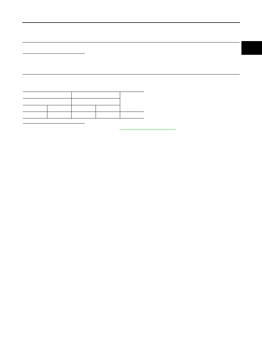
Check harness continuity between ECM harness connector and IPDM E/R harness connector.

Is the inspection result normal?

YES

>> Check intermittent incident. Refer to 

GI-41, "Intermittent Incident"

.

NO

>> Repair or replace error-detected parts.

+

-

Continuity

ECM

IPDM E/R

Connector

Terminal

Connector

Terminal

F80

89

F90

106

Existed

ECK-274

< DTC/CIRCUIT DIAGNOSIS >

[K9K]

P062B ECM

P062B ECM

DTC Logic

INFOID:0000000010289881

DTC DETECTION LOGIC

NOTE:
• If DTC P062B is displayed with DTC P0201, P0202, P0203, or P0204, perform the trouble diagnosis

for DTC P0201, P0202, P0203, or P0204. Refer to 

ECK-97, "DTC Index"

.

DTC CONFIRMATION PROCEDURE

1.

PRECONDITIONING

If DTC Confirmation Procedure has been previously conducted, always turn ignition switch OFF and wait at
least 1 minute before conducting the next test.

>> GO TO 2.

2.

PERFORM DTC CONFIRMATION PROCEDURE

1.

Turn ignition switch ON and wait at least 1 second.

2.

Check DTC.

Is DTC detected?

YES

>> Proceed to 

ECK-274, "Diagnosis Procedure"

.

NO

>> INSPECTION END

Diagnosis Procedure

INFOID:0000000010289882

1.

INSPECTION START

1.

Turn ignition switch ON.

2.

Erase DTC.

3.

Turn ignition switch OFF and wait for 1 minute.

4.

Turn ignition switch ON and wait at least 1 second.

5.

Perform the self-diagnosis.

Is the DTC P062B displayed again?

YES

>> GO TO 2.

NO

>> INSPECTION END

2.

REPLACE ECM

1.

Replace ECM.

2.

Perform 

ECK-131, "Work Procedure"

.

>> INSPECTION END

DTC No.

CONSULT screen terms

(Trouble diagnosis content)

DTC detecting condition

Possible cause

P062B

COMPUTER
(Internal control module fuel in-
jector control performance)
• 1.DEF: VALUES OUTSIDE 

TOLERANCES

• 2.DEF: VOLTAGE TOO LOW
• 3.DEF: VOLTAGE TOO HIGH
• 4.DEF: —
• 5.DEF: —

ECM calculation function is malfunctioning.

• ECM
• Fuel injector

P0638 ELECTRIC THROTTLE CONTROL ACTUATOR FUNCTION

ECK-275

< DTC/CIRCUIT DIAGNOSIS >

[K9K]

C

D

E

F

G

H

I

J

K

L

M

A

ECK

N

P

O

P0638 ELECTRIC THROTTLE CONTROL ACTUATOR FUNCTION

DTC Logic

INFOID:0000000010289883

DTC DETECTION LOGIC

NOTE:
If DTC P0638 is displayed with DTC P0120 or P2100, first perform the trouble diagnosis for DTC P0120
or P2100. Refer to 

ECK-203, "DTC Logic"

 or 

ECK-362, "DTC Logic"

.

DTC CONFIRMATION PROCEDURE

1.

PRECONDITIONING

If DTC Confirmation Procedure has been previously conducted, always turn ignition switch OFF and wait at
least 1 minute before conducting the next test.

>> GO TO 2.

2.

PERFORM DTC CONFIRMATION PROCEDURE

1.

Turn ignition switch ON and wait at least 3 seconds.

2.

Check DTC.

Is DTC detected?

YES

>> Proceed to 

ECK-275, "Diagnosis Procedure"

.

NO

>> INSPECTION END

Diagnosis Procedure

INFOID:0000000010289884

1.

CHECK ECM HARNESS CONNECTOR CONNECTIONS

1.

Turn ignition switch OFF.

2.

Check ECM harness connector connection.

Is the inspection result normal?

YES

>> GO TO 2.

NO

>> Repair or replace error-detected parts.

2.

CHECK ELECTRIC THROTTLE CONTROL ACTUATOR HARNESS CONNECTOR CONNECTIONS

Check electric throttle control actuator harness connector connection.

Is the inspection result normal?

YES

>> GO TO 3.

NO

>> Repair or replace error-detected parts.

3.

CHECK ELECTRIC THROTTLE CONTROL ACTUATOR CIRCUIT FOR OPEN AND SHORT

1.

Turn ignition switch OFF.

2.

Check electric throttle control actuator circuit for open and short.

DTC No.

CONSULT screen terms

(Trouble diagnosis content)

DTC detecting condition

Possible cause

P0638

INLET AIR FLAP POSITION 
CTRL
(Throttle actuator control range/
performance bank 1)
• 1.DEF: NO RESPONSE 

FROM THE VALVE MOTOR

• 2.DEF: INLET FLAP 

BLOCKED CLOSED

• 3.DEF: INLET FLAP 

BLOCKED OPEN

• 4.DEF: CLOSING OF AIR IN-

LET FLAP

• Throttle valve regulation error
• ECM detects an incorrect closed position of the 

throttle valve.

• ECM detects an incorrect fully open position of 

the throttle valve.

• Electric throttle control actuator
• Throttle valve stuck
• Throttle chamber clogged

ECK-276

< DTC/CIRCUIT DIAGNOSIS >

[K9K]

P0638 ELECTRIC THROTTLE CONTROL ACTUATOR FUNCTION

Is the inspection result normal?

YES

>> GO TO 4.

NO

>> Repair or replace error-detected parts.

4.

DTC CONFIRMATION PROCEDURES

1.

Erase DTC.

2.

Perform DTC confirmation procedure again. Refer to 

ECK-275, "DTC Logic"

.

Is the DTC P0638 displayed again?

YES

>> GO TO 5.

NO

>> Check intermittent incident. Refer to 

GI-41, "Intermittent Incident"

.

5.

CHECK ELECTRIC THROTTLE CONTROL ACTUATOR

Perform 

ECK-204, "Component Inspection (Throttle Position Sensor)"

 (throttle position sensor), 

ECK-363,

"Component Inspection"

 (throttle control motor).

Is the inspection result normal?

YES

>> Check intermittent incident. Refer to 

GI-41, "Intermittent Incident"

.

NO

>> GO TO 6.

6.

REPLACE ELECTRIC THROTTLE CONTROL ACTUATOR

1.

Replace electric throttle control actuator.

2.

Perform 

ECK-136, "Work Procedure"

.

>> INSPECTION END

+

-

Continuity

ECM

Electric throttle control actu-

ator

Connector

Terminal

Connector

Terminal

F80

61

F46

2

Existed

67

3

71

4

F81

139

6

140

1

P0641 SENSOR POWER SUPPLY

ECK-277

< DTC/CIRCUIT DIAGNOSIS >

[K9K]

C

D

E

F

G

H

I

J

K

L

M

A

ECK

N

P

O

P0641 SENSOR POWER SUPPLY

DTC Logic

INFOID:0000000010289885

DTC DETECTION LOGIC

DTC CONFIRMATION PROCEDURE

1.

PRECONDITIONING

If DTC Confirmation Procedure has been previously conducted, always turn ignition switch OFF and wait at
least 1 minute before conducting the next test.

>> GO TO 2.

2.

PERFORM DTC CONFIRMATION PROCEDURE

1.

Turn ignition switch ON and wait at least 1 second.

2.

Check DTC.

Is DTC detected?

YES

>> Proceed to 

ECK-277, "Diagnosis Procedure"

.

NO

>> INSPECTION END

Diagnosis Procedure

INFOID:0000000010289886

1.

CHECK SENSOR POWER SUPPLY

1.

Turn ignition switch ON.

2.

Check the voltage between ECM harness connector and ground.

DTC No.

CONSULT screen terms

(Trouble diagnosis content)

DTC detecting condition

Possible cause

P0641

SEN SUPPLY N1 VOL
(Sensor reference voltage “A” 
circuit/open) 
• 1.DEF: VOLTAGE TOO LOW
• 2.DEF: VOLTAGE TOO 

HIGH

• A voltage of sensor power supply is 5.4 V or 

more.

• A voltage of sensor power supply is 4.6 V or 

less.

• Harness or connectors

(The sensor power supply 1 circuit is 
shorted.)

• High pressure EGR volume control 

valve position sensor

• Throttle position sensor
• TC boost sensor
• Low pressure EGR volume control 

valve position sensor

• Exhaust gas pressure sensor
• Camshaft position sensor
• APP sensor 1
• Refrigerant pressure sensor
• Mass air flow sensor
• ECM

ECK-278

< DTC/CIRCUIT DIAGNOSIS >

[K9K]

P0641 SENSOR POWER SUPPLY

Is the inspection result normal?

YES

>> Check intermittent incident. Refer to 

GI-41, "Intermittent Incident"

.

NO

>> GO TO 2.

2.

CHECK SENSOR POWER SUPPLY CIRCUITS

1.

Turn ignition switch OFF.

2.

Check harness for short to power and short to ground, between the following terminals.

Is the inspection result normal?

YES

>> GO TO 3.

NO

>> Repair short to ground or short to power in harness or connectors.

3.

CHECK COMPONENTS

Check the following.
• Accelerator pedal position sensor (sensor 1). Proceed to 

ECK-219, "Diagnosis Procedure"

.

• Low pressure EGR volume control valve position sensor. Proceed to 

ECK-307, "Component Inspection (Low

Pressure EGR Volume Control Valve Motor)"

.

• Exhaust gas pressure sensor. Proceed to 

ECK-244, "Component Inspection (Exhaust Gas Pressure Sen-

sor)"

.

• Camshaft position sensor. Proceed to 

ECK-232, "Component Inspection (Camshaft Position Sensor)"

.

• Mass air flow sensor. Proceed to 

ECK-194, "Component Inspection (Mass Air Flow Sensor)"

.

• Turbocharger boost sensor. Proceed to 

ECK-198, "Component Inspection (Turbocharger Boost Sensor)"

.

• Throttle position sensor. Proceed to 

ECK-204, "Component Inspection (Throttle Position Sensor)"

.

• Refrigerant pressure sensor. Proceed to 

ECK-257, "Diagnosis Procedure"

.

• High pressure EGR volume control valve position sensor. Proceed to 

ECK-240, "Diagnosis Procedure"

.

Is the inspection result normal?

YES

>> Check intermittent incident. Refer to 

GI-41, "Intermittent Incident"

.

+

Voltage

(Approx.)

ECM

Connectors

Terminal

E59

27

Ground

5.0 V

F80

41

61

65

69

73

77

F81

97

101

ECM

Sensor

Connector

Terminal

Name

Connector

Terminal

E59

27

Accelerator pedal position sensor (sensor 1)

E20

4

F80

41

Camshaft position sensor

F118

1

61

Electric throttle control actuator

F46

2

65

Low pressure EGR volume control valve position sensor

F34

1

69

High pressure EGR volume control valve position sensor

F60

6

73

Mass air flow sensor

F91

3

77

Exhaust gas pressure sensor

F110

3

F81

97

Refrigerant pressure sensor

E41

3

101

Turbocharger boost sensor

F5

3

P0641 SENSOR POWER SUPPLY

ECK-279

< DTC/CIRCUIT DIAGNOSIS >

[K9K]

C

D

E

F

G

H

I

J

K

L

M

A

ECK

N

P

O

NO

>> Replace malfunctioning component.

ECK-280

< DTC/CIRCUIT DIAGNOSIS >

[K9K]

P0651 SENSOR POWER SUPPLY

P0651 SENSOR POWER SUPPLY

DTC Logic

INFOID:0000000010289890

DTC DETECTION LOGIC

DTC CONFIRMATION PROCEDURE

1.

PRECONDITIONING

If DTC Confirmation Procedure has been previously conducted, always turn ignition switch OFF and wait at
least 1 minute before conducting the next test.

>> GO TO 2.

2.

PERFORM DTC CONFIRMATION PROCEDURE

1.

Turn ignition switch ON and wait at least 1 second.

2.

Check DTC.

Is DTC detected?

YES

>> Proceed to 

ECK-280, "Diagnosis Procedure"

.

NO

>> INSPECTION END

Diagnosis Procedure

INFOID:0000000010289891

1.

CHECK SENSOR POWER SUPPLY

1.

Turn ignition switch ON.

2.

Check the voltage between ECM harness connector and ground.

Is the inspection result normal?

YES

>> Check intermittent incident. Refer to 

GI-41, "Intermittent Incident"

.

NO

>> GO TO 2.

2.

CHECK SENSOR POWER SUPPLY CIRCUITS

1.

Turn ignition switch OFF.

2.

Check harness for short to power and short to ground, between the following terminals.

DTC No.

CONSULT screen terms

(Trouble diagnosis content)

DTC detecting condition

Possible cause

P0651

SEN SUPPLY N2 VOL
(Sensor reference voltage “B” 
circuit/open)
• 1.DEF: VOLTAGE TOO 

LOW

• 2.DEF: VOLTAGE TOO 

HIGH

• A voltage of sensor power supply is 5.4 V 

or more.

• A voltage of sensor power supply is 4.6 V 

or less.

• Harness or connectors

(The sensor power supply 2 circuit is 
shorted.)

• Exhaust electric throttle position sen-

sor

• Exhaust gas pressure sensor
• DPF differential pressure sensor
• APP sensor 2
• Refrigerant pressure sensor

+

Voltage

(Approx.)

ECM

Connectors

Terminal

E59

23

Ground

5.0 V

F80

53

57

77

F81

97

P0651 SENSOR POWER SUPPLY

ECK-281

< DTC/CIRCUIT DIAGNOSIS >

[K9K]

C

D

E

F

G

H

I

J

K

L

M

A

ECK

N

P

O

Is the inspection result normal?

YES

>> GO TO 3.

NO

>> Repair short to ground or short to power in harness or connectors.

3.

CHECK COMPONENTS

Check the following.
• Accelerator pedal position sensor (sensor 2). Proceed to 

ECK-365, "Diagnosis Procedure"

.

• DPF pressure sensor. Proceed to 

ECK-295, "Component Inspection (DPF Differential Pressure Sensor)"

.

• Exhaust electric throttle control actuator. Proceed to 

ECK-297, "Component Inspection (Exhaust Throttle

Control Motor)"

.

• Exhaust gas pressure sensor. Proceed to 

ECK-244, "Component Inspection (Exhaust Gas Pressure Sen-

sor)"

.

• Refrigerant pressure sensor. Proceed to 

ECK-257, "Diagnosis Procedure"

.

Is the inspection result normal?

YES

>> Check intermittent incident. Refer to 

GI-41, "Intermittent Incident"

.

NO

>> Replace malfunctioning component.

ECM

Sensor

Connector

Terminal

Name

Connector

Terminal

E59

23

APP sensor 2

E20

5

F80

53

DPF differential pressure sensor

F11

1

57

Exhaust electric throttle control actuator

F59

1

77

Exhaust gas pressure sensor

F110

3

F81

97

Refrigerant pressure sensor

E41

3

ECK-282

< DTC/CIRCUIT DIAGNOSIS >

[K9K]

P0657 ECM RELAY

P0657 ECM RELAY

DTC Logic

INFOID:0000000010289892

DTC DETECTION LOGIC

NOTE:
If this DTC is detected, first confirm self-diagnostic result in IPDM E/R.

DTC CONFIRMATION PROCEDURE

1.

PRECONDITIONING

If DTC Confirmation Procedure has been previously conducted, always turn ignition switch OFF and wait at
least 1 minute before conducting the next test.

>> GO TO 2.

2.

PERFORM DTC CONFIRMATION PROCEDURE

1.

Turn ignition switch ON and wait at least 1 second.

2.

Check DTC.

Is DTC detected?

YES

>> Proceed to 

ECK-282, "Diagnosis Procedure"

.

NO

>> INSPECTION END

Diagnosis Procedure

INFOID:0000000010289893

1.

CHECK ECM RELAY POWER SUPPLY CIRCUIT

1.

Turn ignition switch ON.

2.

Check ECM relay circuit for open and short.

Is the inspection result normal?

YES

>> GO TO 2.

NO

>> Perform trouble diagnosis for power supply circuit.

2.

CHECK ECM RELAY CIRCUIT FOR OPEN AND SHORT

1.

Turn ignition switch OFF.

2.

Check the continuity between ECM harness connector and ground ECM relay harness connector.

DTC 

No.

CONSULT screen terms

(Trouble diagnosis content)

DTC detecting condition

Possible cause

P0657

MAIN RELAY CONTROL 
CIRCUIT
(Actuator supply voltage “A” 
circuit/open)
• CC.0: SHORT CIRCUIT TO 

EARTH

• CO: OPEN CIRCUIT

• ECM detects ECM relay control circuit is short to 

ground. (ECM relay always ON)

• Harness or connectors

(ECM relay control circuit is short-
ed.)

• ECM  relay

+

-

Voltage

IPDM E/R

Connector

Terminal

F90

96

Ground

Battery voltage

103

P0657 ECM RELAY

ECK-283

< DTC/CIRCUIT DIAGNOSIS >

[K9K]

C

D

E

F

G

H

I

J

K

L

M

A

ECK

N

P

O

Is the inspection result normal?

YES

>> Check intermittent incident. Refer to 

GI-41, "Intermittent Incident"

.

NO

>> Repair or replace error-detected parts.

+

-

Continuity

ECM

IPDM E/R

Connector

Terminal

Connector

Terminal

F80

93

F90

103

Existed

94

96

ECK-284

< DTC/CIRCUIT DIAGNOSIS >

[K9K]

P0697 SENSOR POWER SUPPLY

P0697 SENSOR POWER SUPPLY

DTC Logic

INFOID:0000000010289894

DTC DETECTION LOGIC

DTC CONFIRMATION PROCEDURE

1.

PRECONDITIONING

If DTC Confirmation Procedure has been previously conducted, always turn ignition switch OFF and wait at
least 1 minute before conducting the next test.

>> GO TO 2.

2.

PERFORM DTC CONFIRMATION PROCEDURE

1.

Turn ignition switch ON and wait at least 1 second.

2.

Check DTC.

Is DTC detected?

YES

>> Proceed to 

ECK-284, "Diagnosis Procedure"

.

NO

>> INSPECTION END

Diagnosis Procedure

INFOID:0000000010289895

1.

CHECK SENSOR POWER SUPPLY

1.

Turn ignition switch OFF.

2.

Disconnect fuel rail pressure (FRP) sensor harness connector.

3.

Turn ignition switch ON.

4.

Check the voltage between FRP sensor harness connector and ground.

Is the inspection result normal?

YES

>> Check intermittent incident. Refer to 

GI-41, "Intermittent Incident"

.

NO

>> GO TO 2.

2.

CHECK SENSOR POWER SUPPLY CIRCUITS

1.

Turn ignition switch OFF.

2.

Disconnect ECM harness connector.

3.

Check harness for short to power and short to ground, between the following terminals.

Is the inspection result normal?

DTC 

No.

CONSULT screen terms

(Trouble diagnosis content)

DTC detecting condition

Possible cause

P0697

SEN SUPPLY N-3 VOL
(Sensor reference voltage “C” 
circuit/open)
• 1.DEF: VOLTAGE TOO 

LOW

• 2.DEF: VOLTAGE TOO 

HIGH

• A voltage of sensor power supply is more than 5.4 V.
• A voltage of sensor power supply is less than 4.6 V.

• Harness or connectors
• Fuel rail pressure sensor

+

Voltage

(Approx.)

FRP sensor

Connectors

Terminal

F40

3

Ground

5 V

ECM

Sensor

Connector

Terminal

Name

Connector

Terminal

F80

45

Fuel rail pressure sensor

F40

3

P0697 SENSOR POWER SUPPLY

ECK-285

< DTC/CIRCUIT DIAGNOSIS >

[K9K]

C

D

E

F

G

H

I

J

K

L

M

A

ECK

N

P

O

YES

>> GO TO 3.

NO

>> Repair short to ground or short to power in harness or connectors.

3.

CHECK COMPONENTS

Check FRP sensor. Proceed to 

ECK-209, "Diagnosis Procedure"

.

Is the inspection result normal?

YES

>> Check intermittent incident. Refer to 

GI-41, "Intermittent Incident"

.

NO

>> Replace malfunctioning component.

ECK-286

< DTC/CIRCUIT DIAGNOSIS >

[K9K]

P0806 CLUTCH SWITCH

P0806 CLUTCH SWITCH

Description

INFOID:0000000010434259

When the clutch pedal is depressed, clutch interlock switch turns ON and clutch pedal position switch turns
OFF. ECM detects the state of the clutch pedal by those two types of input (ON/OFF signal).

DTC Logic

INFOID:0000000010434260

DTC DETECTION LOGIC

DTC CONFIRMATION PROCEDURE

1.

PRECONDITIONING

If DTC Confirmation Procedure has been previously conducted, always turn ignition switch OFF and wait at
least 10 seconds before conducting the next test. 
TESTING CONDITION:
Before performing the following procedure, confirm that battery voltage is more than 10 V at idle.

>> GO TO 2.

2.

PERFORM DTC CONFIRMATION PROCEDURE FOR MALFUNCTION A

1.

Turn ignition switch ON.

2.

Fully depress clutch pedal.

3.

Fully release clutch pedal.

4.

Repeat steps 2 and 3 for five times.

5.

Check DTC.

Is DTC detected?

YES

>> Proceed to 

ECK-287, "Diagnosis Procedure"

.

NO

>> GO TO 3.

3.

PERFORM DTC CONFIRMATION PROCEDURE FOR MALFUNCTION B

Perform component function check. Refer to 

ECK-286, "Component Function Check"

.

NOTE:
Use component function check to check the overall function of the clutch switch circuit. During this
check, a DTC might not be confirmed.

Is the inspection result normal?

YES

>> INSPECTION END

NO

>> Proceed to 

ECK-287, "Diagnosis Procedure"

.

Component Function Check

INFOID:0000000010434261

1.

PERFORM COMPONENT FUNCTION CHECK

1.

Turn ignition switch ON.

2.

Check the voltage between ECM harness connector terminals as per the following conditions.

DTC No.

CONSULT screen terms

(Trouble diagnosis con-

tent)

DTC detecting condition

Possible cause

P0806


(Clutch position sensor 
circuit range/perfor-
mance)
• 1.DEF: IMPLAUSI-

BLE SIGNAL

A)

ON signals from the clutch interlock 
switch and the clutch pedal position 
switch are sent to the ECM at the 
same time.

• Harness or connectors

(Clutch interlock switch circuit is open or shorted.)
(Clutch pedal position switch circuit is open or 
shorted.)

• Clutch interlock switch
• Clutch pedal position switch
• Incorrect clutch interlock switch installation
• Incorrect clutch pedal position switch installation

B)

Clutch interlock switch ON signal is 
not sent to ECM for extremely long 
time.

P0806 CLUTCH SWITCH

ECK-287

< DTC/CIRCUIT DIAGNOSIS >

[K9K]

C

D

E

F

G

H

I

J

K

L

M

A

ECK

N

P

O

Is the inspection result normal?

YES

>> INSPECTION END

NO

>> Proceed to 

ECK-287, "Diagnosis Procedure"

.

Diagnosis Procedure

INFOID:0000000010434262

1.

CHECK OVERALL FUNCTION-1

 With CONSULT

1.

Turn ignition switch ON.

2.

Select “CLUTCH PEDAL SWITCH” in “DATA MONITOR” mode of “ENGINE” using CONSULT.

3.

Check “CLUTCH PEDAL SWITCH” indication as per the following conditions.

Without CONSULT

1.

Turn ignition switch ON.

2.

Check the voltage between ECM harness connector terminals as per the following conditions.

Is the inspection result normal?

YES

>> GO TO 2.

NO

>> GO TO 3.

2.

CHECK OVERALL FUNCTION-2

Check the voltage between ECM harness connector terminals as per the following conditions.

Is the inspection result normal?

YES

>> Check intermittent incident. Refer to 

GI-41, "Intermittent Incident"

.

NO

>> GO TO 6.

3.

CHECK CLUTCH PEDAL POSITION SWITCH GROUND CIRCUIT

1.

Turn ignition switch OFF.

2.

Disconnect clutch pedal position switch harness connector.

ECM

Condition

Voltage

(Approx.)

Connector

+

-

Terminal

E59

9

(Clutch pedal position switch signal)

25

Clutch pedal

Fully released

0 V

Fully depressed

Battery voltage

6

(Clutch interlock switch signal)

Fully released

0 V

Fully depressed

Battery voltage

Monitor item

Condition

Indication

CLUTCH PEDAL 
SWITCH

Clutch pedal

Fully released

On

Fully depressed

Off

ECM

Condition

Voltage

(Approx.)

Connector

+

-

Terminal

E59

9

25

Clutch pedal

Fully released

0 V

Fully depressed

Battery voltage

ECM

Condition

Voltage

(Approx.)

Connector

+

-

Terminal

E59

6

25

Clutch pedal

Fully released

0 V

Fully depressed

Battery voltage

ECK-288

< DTC/CIRCUIT DIAGNOSIS >

[K9K]

P0806 CLUTCH SWITCH

3.

Check the continuity between clutch pedal position switch harness connector and ground.

4.

Also check harness for short to power.

Is the inspection result normal?

YES

>> GO TO 4.

NO

>> Repair open circuit or short to power in harness or connectors.

4.

CHECK CLUTCH PEDAL POSITION SWITCH INPUT SIGNAL CIRCUIT

1.

Disconnect ECM harness connector.

2.

Check the continuity between clutch pedal position switch harness connector and ECM harness connec-
tor.

3.

Also check harness for short to ground and to power.

Is the inspection result normal?

YES

>> GO TO 5.

NO

>> Repair or replace error-detected parts.

5.

CHECK CLUTCH PEDAL POSITION SWITCH

Check clutch pedal position switch. Refer to 

ECK-289, "Component Inspection (Clutch Pedal Position Switch)"

.

Is the inspection result normal?

YES

>> Check intermittent incident. Refer to 

GI-41, "Intermittent Incident"

.

NO

>> Replace error-detected parts.

6.

CHECK CLUTCH INTERLOCK SWITCH POWER SUPPLY CIRCUIT

1.

Turn ignition switch OFF.

2.

Disconnect clutch interlock switch harness connector.

3.

Turn ignition switch ON.

4.

Check the voltage between clutch interlock switch harness connector and ground.

Is the inspection result normal?

YES

>> GO TO 7.

NO

>> Perform the trouble diagnosis for power supply circuit.

7.

CHECK CLUTCH INTERLOCK SWITCH INPUT SIGNAL CIRCUIT

1.

Turn ignition switch OFF.

2.

Disconnect ECM harness connector. 

3.

Check the continuity between clutch interlock switch harness connector and ECM harness connector.

+

Continuity

Clutch pedal position switch

Connector

Terminal

E2

2

Ground

Existed

+

Continuity

Clutch pedal position switch

ECM

Connector

Terminal

Connector

Terminal

E2

1

E59

9

Existed

+

Voltage

(Approx.)

Clutch interlock switch

Connector

Terminal

E52

1

Ground

Battery voltage


Content      ..     16      17      18      19     ..