Qashqai J11. Engine control system (R9M) - part 14
EC9-210
< DTC/CIRCUIT DIAGNOSIS >
[R9M]
P0190 FRP SENSOR
Is the inspection result normal?
YES
>> GO TO 5.
NO
>> Perform trouble diagnosis for power supply circuit.
5.
CHECK FUEL RAIL PRESSURE SENSOR CIRCUIT FOR OPEN AND SHORT
1.
Turn ignition switch OFF.
2.
Check fuel rail pressure sensor circuit for open and short.
Is the inspection result normal?
YES
>> Replace fuel rail pressure sensor.
NO
>> Repair or replace error-detected parts.
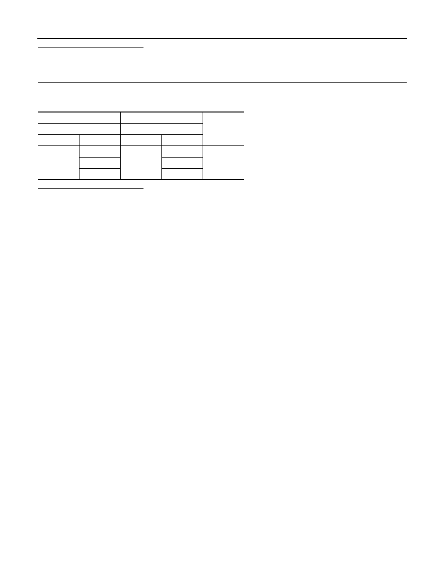
+
-
Continuity
ECM
Fuel rail pressure sensor
Connector
Terminal
Connector
Terminal
F82
73
F86
1
Existed
77
2
91
3