Qashqai J11. Audio, Visual & Navigation System - part 17
 

  Index      Nissan     Qashqai J11. Audio, Visual & Navigation System. Service and Repair Manual


Search            copyright infringement  


Content      ..     15      16      17     


Qashqai J11. Audio, Visual & Navigation System - part 17


AV

NORMAL OPERATING CONDITION

AV-257

< SYMPTOM DIAGNOSIS >

[NAVIGATION]

C

D

E

F

G

H

I

J

K

L

M

B

A

O

P

Location Correction by Map-Matching is Slow

• The map-matching function needs to refer to the data of the surrounding area. It is necessary to drive some

distance for the function to work.

• Because map-matching operates on this principle, when there are many roads running in similar directions

in the surrounding area, no matching determination may be made. The location may not be corrected until
some special feature is found.

Name of Road is Not Displayed

The current road name may not be displayed if there are no road names displayed on the map screen.

Contents of Display Differ for Birdview™ and the (Flat) Map Screen

Difference of the BIRDVIEW™ screen from the flat map screen are as follows.
• The current place name displays names which are primarily in the direction of vehicle travel.
• The amount of time before the vehicle travel or turn angle is updated on the screen is longer than for the

(flat) map display.

• The conditions for display of place names, roads, and other data are different for nearby areas and for more

distant areas.

• Some thinning of the character data is done to prevent the display becoming too complex. In some cases

and in some locations, the display contents may differ.

• The same place name, street name, etc. may be displayed multiple times.

Vehicle Mark Shows a Position Which is Completely Wrong

In the following cases, the vehicle mark may appear on completely different position in the map depending on
the GPS satellite signal receiving conditions. In this case, perform location correction and direction correction.
• When location correction has not been done
- If the receiving conditions of the GPS satellite signal is poor, if the vehicle mark becomes out of place, it may

move to a completely different location and not come back if location correction is not done. The position will
be corrected if the GPS signal can be received.

• When the vehicle has traveled by ferry, or when the vehicle has been being towed

Precautions 
for driving

Just after the engine is started

If the vehicle is driven just after the engine 
is started when the gyroscope (angular 
speed sensor) correction is not completed, 
the vehicle can lose its direction and may 
have deviated from the correct location.

Wait for a short while before 
driving after starting the engine.

Continuous driving without stopping

When driving long distances without stop-
ping, direction errors may accumulate, and 
the current-location mark may deviate from 
the correct road.

Stop and adjust the orientation.

Abusive driving

Spinning the wheels or engaging in other 
kinds of abusive driving may result in the 
system being unable perform correct detec-
tion, and may cause the vehicle mark to de-
viate from the correct road.

If after travelling about 10 km (6 
miles) the correct location has 
not been restored, perform lo-
cation correction and, if neces-
sary, direction correction.

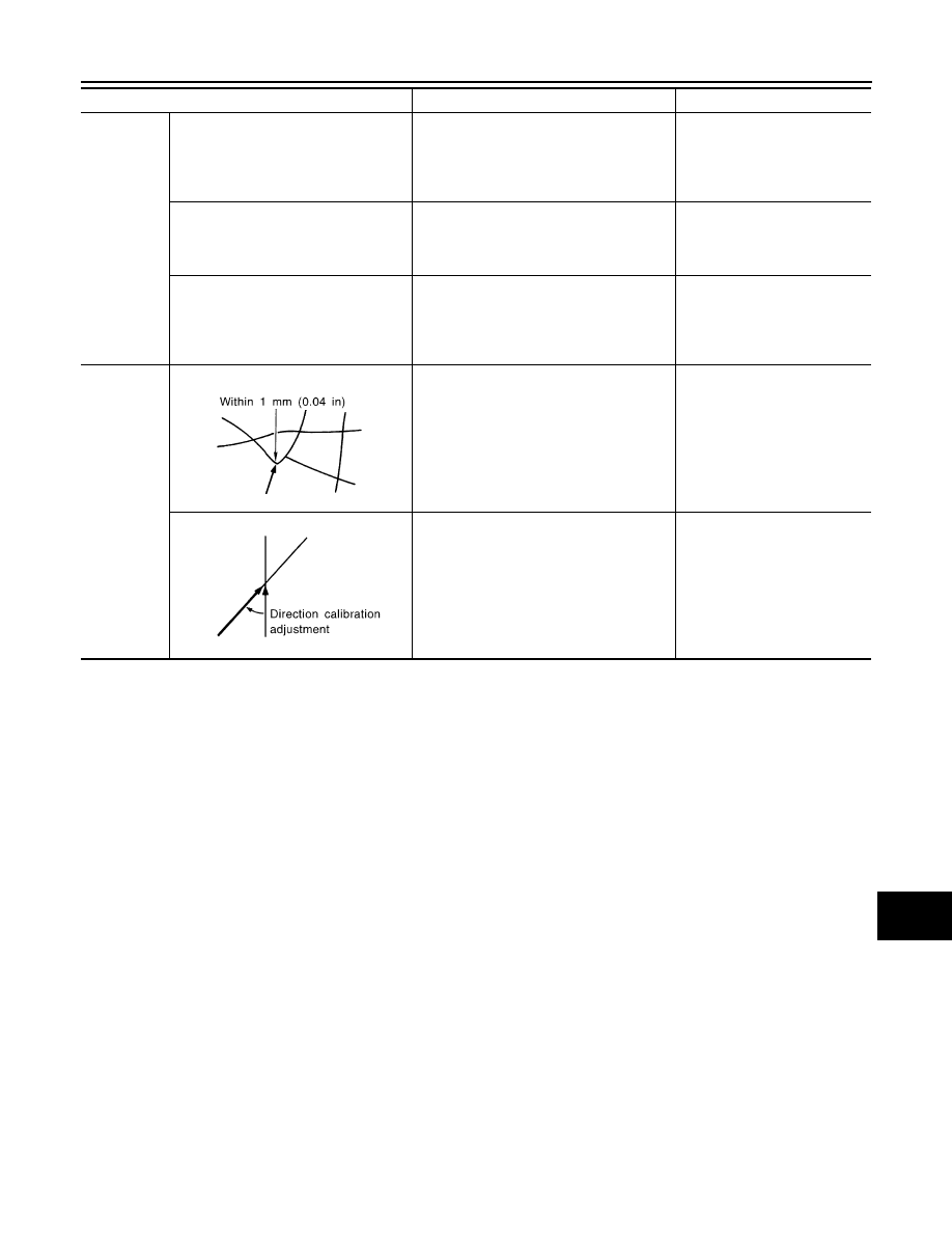
How to cor-
rect location

Position correction accuracy

If the accuracy of location settings is poor, 
accuracy may be reduced when the correct 
road cannot be found, particularly in places 
where there are many roads.

Enter in the road displayed on 
the screen with an accuracy of 
approx. 1mm.
Caution: Whenever possible, 
use detailed map for the correc-
tion.

Direction when location is corrected

If the accuracy of location settings during 
correction is poor, accuracy may be re-
duced afterwards.

Perform direction correction.

Cause (condition)

–: While driving

ooo: Display

Driving condition

Remarks (correction, etc.)

SEL701V

SEL702V

AV-258

< SYMPTOM DIAGNOSIS >

[NAVIGATION]

NORMAL OPERATING CONDITION

- Because calculation of the current location cannot be done when traveling with the ignition off, for example

when traveling by ferry or when being towed, the location before travel is displayed. If the precise location
can be detected with GPS, the location will be corrected.

Vehicle Mark Jumps

In the following cases, the vehicle mark may appear to jump as a result of automatic correction of the current
location.
• When map matching has been done
- If the current location and the vehicle mark are different when map matching is done, the vehicle mark may

seem to jump. At this time, the location may be “corrected” to the wrong road or to a location which is not on
a road.

• When GPS location correction has been done
- If the current location and the vehicle mark are different when the location is corrected using GPS measure-

ments, the vehicle mark may seem to jump. At this time, the location may be “corrected” to a location which
is not on a road.

Vehicle Mark is in a River or Sea

The navigation system moves the vehicle mark with no distinction between land and rivers or sea. If the vehi-
cle mark is somehow out of place, it may appear that the vehicle is driving in a river or the sea.

Vehicle Mark Automatically Rotates

The system wrongly memorizes the rotating status as stopping when the ignition switch is turned ON with the
turntable rotating. That causes the vehicle mark to rotate when the vehicle is stopped.

When Driving on Same Road, Sometimes Vehicle Mark is in Right Place and Sometimes it is in Wrong Place

The conditions of the GPS antenna (GPS data) and gyroscope (angular speed sensor) change gradually.
Depending on the road traveled and the operation of the steering wheel, the location detection results will be
different. Therefore, even on a road on which the location has never been wrong, conditions may cause the
vehicle mark to deviate.

AV

AV CONTROL UNIT

AV-259

< REMOVAL AND INSTALLATION >

[NAVIGATION]

C

D

E

F

G

H

I

J

K

L

M

B

A

O

P

REMOVAL AND INSTALLATION

AV CONTROL UNIT

Exploded View

INFOID:0000000010435739

Removal and Installation

INFOID:0000000010435740

REMOVAL

CAUTION:

• Before disconnecting the AV control unit and battery terminals, turn the ignition switch OFF and wait

at least 30 seconds.

• Before replacing AV control unit, perform READ “CONFIGURATION” to save current vehicle specifi-

cation. Refer to 

AV-179, "CONFIGURATION (AV CONTROL UNIT) : Configuration List"

.

NOTE:
After the ignition switch is turned OFF, the AV control unit continues operating for approximately 30 seconds.
Therefore, data corruption may occur if battery voltage is cut off within 30 seconds. 

1.

Disconnect the negative battery terminal. Refer to 

PG-155, "Removal and Installation"

.

2.

Remove A/C switch (AUTOMATIC AIR CONDITIONING) or front air control (MANUAL AIR CONDITION-
ING).

3.

Remove instrument finisher B. Refer to 

IP-12, "Exploded View"

.

4.

Remove instrument finisher E. Refer to 

IP-12, "Exploded View"

.

5.

Remove the AV control unit screws, then pull out the AV control unit.

6.

Disconnect the harness connectors from the AV control unit and remove.

7.

Remove the AV control unit bracket (LH/RH) screws and the AV control unit brackets (LH/RH) (if neces-
sary).

INSTALLATION

Installation is in the reverse order of removal.

1.

AV control unit bracket (LH)

2.

AV control unit

3.

AV control unit bracket (RH)

AWNIA3339ZZ

AV-260

< REMOVAL AND INSTALLATION >

[NAVIGATION]

AV CONTROL UNIT

CAUTION:

When replacing AV control unit, perform “WRITE CONFIGURATION”. Refer to 

AV-179, "CONFIGURA-

TION (AV CONTROL UNIT) : Configuration List"

.

AV

STEERING SWITCH

AV-261

< REMOVAL AND INSTALLATION >

[NAVIGATION]

C

D

E

F

G

H

I

J

K

L

M

B

A

O

P

STEERING SWITCH

Exploded View

INFOID:0000000010435741

Removal and Installation

INFOID:0000000010435742

REMOVAL

NOTE:
The steering switches are serviced as an assembly.

1.

Remove steering wheel. Refer to 

ST-8, "Exploded View"

.

2.

Release pawls on the steering wheel rear finisher and remove.

3.

Remove screws (A) and steering switches (1) from steering
wheel (2).

INSTALLATION

Installation is in the reverse order of removal.

1.

Steering wheel rear finisher

2.

Steering wheel

3.

Steering switches

Pawl

AWNIA3342ZZ

AWNIA3326ZZ

AV-262

< REMOVAL AND INSTALLATION >

[NAVIGATION]

FRONT TWEETER

FRONT TWEETER

Removal and Installation

INFOID:0000000010435743

REMOVAL

1.

Remove defroster grille. Refer to 

IP-12, "Exploded View"

.

2.

Remove bolts and pull out the front tweeter.

3.

Disconnect the harness connector from the front tweeter and remove.

INSTALLATION

Installation is in the reverse order of removal.

AV

FRONT DOOR SPEAKER

AV-263

< REMOVAL AND INSTALLATION >

[NAVIGATION]

C

D

E

F

G

H

I

J

K

L

M

B

A

O

P

FRONT DOOR SPEAKER

Exploded View

INFOID:0000000010435744

Removal and Installation

INFOID:0000000010435745

REMOVAL

1.

Remove front door finisher. Refer to 

INT-12, "FRONT DOOR FINISHER : Exploded View"

.

2.

Remove front door speaker bolts, then pull out front door speaker.

3.

Disconnect the harness connector from front door speaker and remove. 

INSTALLATION

Installation is in the reverse order of removal.

ALNIA1580ZZ

1.

Front door speaker

AV-264

< REMOVAL AND INSTALLATION >

[NAVIGATION]

REAR DOOR SPEAKER

REAR DOOR SPEAKER

Exploded View

INFOID:0000000010435746

Removal and Installation

INFOID:0000000010435747

REMOVAL

1.

Remove rear door finisher. Refer to 

INT-15, "REAR DOOR FINISHER : Exploded View"

.

2.

Remove rear door speaker bolts, then pull out rear door speaker.

3.

Disconnect the harness connector from the rear door speaker and remove.

INSTALLATION

Installation is in the reverse order of removal.

1.

Rear door speaker

ALNIA1581ZZ

AV

USB INTERFACE AND AUX IN JACK

AV-265

< REMOVAL AND INSTALLATION >

[NAVIGATION]

C

D

E

F

G

H

I

J

K

L

M

B

A

O

P

USB INTERFACE AND AUX IN JACK

Removal and Installation

INFOID:0000000010435748

REMOVAL

1.

Remove center console. Refer to 

IP-18, "Exploded View"

.

2.

Release the pawls (A) on the back of USB interface and AUX in
jack (2).

INSTALLATION

Installation is in the reverse order of removal.

ALNIA1582ZZ

AV-266

< REMOVAL AND INSTALLATION >

[NAVIGATION]

MICROPHONE

MICROPHONE

Removal and Installation

INFOID:0000000010435749

REMOVAL

1.

Remove the map lamp assembly. Refer to 

INT-24, "Exploded View"

.

2.

Release harness connector (A) by sliding rearward to remove
from the pawl (B).

3.

Release pawls (C) and remove the microphone (1) from the
front room/map lamp assembly.

INSTALLATION

Installation is in the reverse order of removal.

ALNIA1583ZZ

AV

AROUND VIEW MONITOR CONTROL UNIT

AV-267

< REMOVAL AND INSTALLATION >

[NAVIGATION]

C

D

E

F

G

H

I

J

K

L

M

B

A

O

P

AROUND VIEW MONITOR CONTROL UNIT

Exploded View

INFOID:0000000010435750

Removal and Installation

INFOID:0000000010435751

REMOVAL

CAUTION:

Before replacing around view monitor control unit, save or print current vehicle specification with
CONSULT configuration before replacement. Refer to 

AV-177, "ADDITIONAL SERVICE WHEN

REPLACING AROUND VIEW MONITOR CONTROL UNIT : Work Procedure"

.

1.

Remove glove box assembly. Refer to 

IP-12, "Exploded View"

.

2.

Remove around view monitor control unit screws.

3.

Disconnect the harness connector from the around view monitor control unit and remove.

INSTALLATION

Installation is in the reverse order of removal.

CAUTION:

• Replace the around view monitor control unit if it has been dropped or sustained an impact.
• When replacing around view monitor control unit, you must perform "After Replace ECU" with CON-

SULT. Refer to 

AV-177, "ADDITIONAL SERVICE WHEN REPLACING AROUND VIEW MONITOR CON-

TROL UNIT : Work Procedure"

.

NOTE:
Perform camera image calibration. Refer to 

AV-181, "CALIBRATING CAMERA IMAGE (AROUND VIEW

MONITOR) : Work Procedure"

.

ALNIA1600ZZ

1.

Around view monitor control unit A.

Harness connector

AV-268

< REMOVAL AND INSTALLATION >

[NAVIGATION]

FRONT CAMERA

FRONT CAMERA

Exploded View

INFOID:0000000010435752

Removal and Installation

INFOID:0000000010435753

REMOVAL

1.

Remove the front grille. Refer to 

EXT-25, "Exploded View"

.

2.

Remove screws and front camera.

INSTALLATION

Installation is in the reverse order of removal.
NOTE:
Perform camera image calibration. Refer to 

AV-181, "CALIBRATING CAMERA IMAGE (AROUND VIEW

MONITOR) : Work Procedure"

.

1.

Front grille

2.

Front camera

ALNIA1612ZZ

AV

SIDE CAMERA

AV-269

< REMOVAL AND INSTALLATION >

[NAVIGATION]

C

D

E

F

G

H

I

J

K

L

M

B

A

O

P

SIDE CAMERA

Removal and Installation

INFOID:0000000010435754

REMOVAL

1.

Remove door mirror rear finisher (2). Refer to 

MIR-31,

"Exploded View"

.

2.

Remove screws (A) and side camera (1).

: Pawl

INSTALLATION

Installation is in the reverse order of removal.

CAUTION:

Perform camera image calibration (if equipped with around view camera). Refer to 

AV-180, "CALI-

BRATING CAMERA IMAGE (AROUND VIEW MONITOR) : Description"

.

ALLIA1383ZZ

AV-270

< REMOVAL AND INSTALLATION >

[NAVIGATION]

REAR VIEW CAMERA

REAR VIEW CAMERA

Removal and Installation

INFOID:0000000010435755

REMOVAL

1.

Remove the back door outer finisher. Refer to 

EXT-45, "Exploded View"

.

2.

Disconnect washer tubes (1,3) and air tube (2) (if equipped).

3.

Release pawl (B), disconnect harness connector (A) from rear
view camera and remove.

INSTALLATION

Installation is in the reverse order of removal.

AWNIA3329ZZ

AV

GPS ANTENNA

AV-271

< REMOVAL AND INSTALLATION >

[NAVIGATION]

C

D

E

F

G

H

I

J

K

L

M

B

A

O

P

GPS ANTENNA

Removal and Installation

INFOID:0000000010435756

REMOVAL

1.

Remove instrument panel. Refer to 

IP-12, "Exploded View"

.

2.

Remove screw and the GPS antenna.

INSTALLATION

Installation is in the reverse order of removal.

AV-272

< REMOVAL AND INSTALLATION >

[NAVIGATION]

AUDIO ANTENNA

AUDIO ANTENNA

Removal and Installation

INFOID:0000000010435757

REMOVAL

1.

Remove the luggage side upper finisher (RH). Refer to 

INT-28, "Exploded View"

.

2.

Partially lower headlining (rear). Refer to 

INT-24, "Exploded View"

.

3.

Disconnect harness connectors from antenna feeder.

4.

Remove nut from audio antenna and remove.

INSTALLATION

Installation is in the reverse order of removal.

CAUTION:

If the audio antenna nut is not properly tightened, lower sensitivity of the antenna may be experi-
enced. If the nut is over tightened, this will deform the roof panel. 

Audio antenna nut

: 6.5 N·m (0.66 kg-m, 58 in-lb)

AV

ANTENNA FEEDER

AV-273

< REMOVAL AND INSTALLATION >

[NAVIGATION]

C

D

E

F

G

H

I

J

K

L

M

B

A

O

P

ANTENNA FEEDER

Feeder Layout

INFOID:0000000010435758

ANTENNA FEEDER LAYOUT

1.

Antenna base (antenna amp. and 
satellite antenna)

2.

Rod Antenna

3.

M394

4.

M399

E1NIA0073ZZ


Content      ..     15      16      17