Qashqai J11. Audio, Visual & Navigation System - part 16


  Index      Nissan     Qashqai J11. Audio, Visual & Navigation System. Service and Repair Manual


Search            copyright infringement  


Content      ..     14      15      16      17     ..


Qashqai J11. Audio, Visual & Navigation System - part 16


AV

STEERING SWITCH

AV-241

< DTC/CIRCUIT DIAGNOSIS >

[NAVIGATION]

C

D

E

F

G

H

I

J

K

L

M

B

A

O

P

STEERING SWITCH

Diagnosis Procedure

INFOID:0000000010435734

Regarding Wiring Diagram information, refer to 

AV-159, "Wiring Diagram"

.

1.

CHECK STEERING WHEEL AUDIO CONTROL SWITCH RESISTANCE

1.

Turn ignition switch OFF.

2.

Disconnect combination switch connector M66.

3.

Check resistance between the terminals of combination switch connector M66.

Is the inspection result normal?

YES

>> GO TO 2.

NO

>> Replace steering switches. Refer to 

AV-261, "Removal and Installation"

.

2.

CHECK HARNESS BETWEEN COMBINATION METER AND COMBINATION SWITCH

1.

Disconnect combination meter connector M51 and combination switch connector M66.

2.

Check continuity between combination meter connector M51 and combination switch connector M66.

3.

Check continuity between combination meter connector M51 and ground.

Is the inspection result normal?

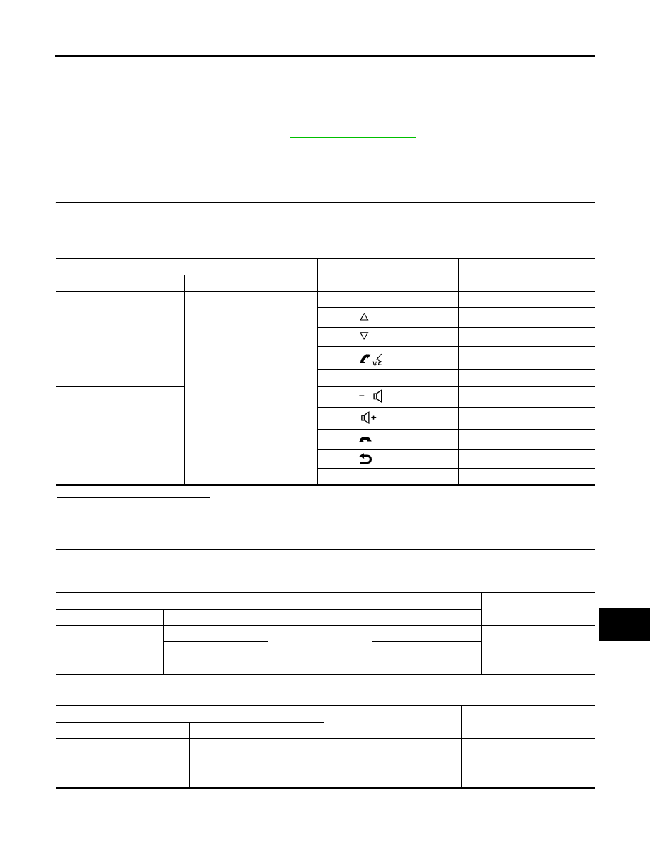
Combination switch connector M66

Condition

Resistance 

(Approx.)

Terminal

Terminal

29

23

Depress SOURCE switch.

1

Depress  

switch.

121

Depress  

switch.

321

Depress  

switch.

723

Depress ENTER switch.

2023

24

Depress  

switch.

1

Depress  

switch.

121

Depress  

switch. 

321

Depress  

switch. 

723

Depress DISPLAY switch. 

2023

Combination meter

Combination switch 

Continuity

Connector

Terminal

Connector

Terminal

M51

22

M66

29

Yes

23

24

21

23

Combination meter

Ground

Continuity

Connector

Terminal

M51

22

No

23

21

AV-242

< DTC/CIRCUIT DIAGNOSIS >

[NAVIGATION]

STEERING SWITCH

YES

>> GO TO 3.

NO

>> Repair or replace harness or connectors.

3.

CHECK COMBINATION SWITCH

Check continuity between combination switch connectors M66 and M303.

Is the inspection result normal?

YES

>> INSPECTION END.

NO

>> Replace spiral cable. Refer to 

SR-17, "Exploded View"

.

Combination switch 

Continuity

Connector

Terminal

Connector

Terminal

M66

29

M303

5

Yes

24

10

23

4

AV

USB CONNECTOR

AV-243

< DTC/CIRCUIT DIAGNOSIS >

[NAVIGATION]

C

D

E

F

G

H

I

J

K

L

M

B

A

O

P

USB CONNECTOR

Diagnosis Procedure

INFOID:0000000010435735

Regarding Wiring Diagram information, refer to 

AV-159, "Wiring Diagram"

.

1.

CHECK USB INTERFACE HARNESS CONTINUITY

1.

Turn ignition switch OFF.

2.

Disconnect AV control unit connector and USB interface connector M384.

3.

Check continuity between AV control unit connector and USB interface connector M384.

Is the inspection result normal?

YES

>> Replace the USB interface. Refer to 

AV-265, "Removal and Installation"

.

NO

>> Repair or replace harness or connectors.

AV control unit

USB interface 

Continuity

Connector

Terminal

Connector

Terminal

M

58

M384

5

Yes

61

6

60

7

59

8

62

9

AV-244

< DTC/CIRCUIT DIAGNOSIS >

[NAVIGATION]

AUXILIARY INPUT JACK

AUXILIARY INPUT JACK

Diagnosis Procedure

INFOID:0000000010435736

Regarding Wiring Diagram information, refer to 

AV-159, "Wiring Diagram"

.

1.

CHECK AUX IN JACK HARNESS CONTINUITY

1.

Turn ignition switch OFF.

2.

Disconnect AV control unit connector M49 and AUX in jack connector M13.

3.

Check continuity between AV control unit connector M49 and AUX in jack connector M13.

4.

Check continuity between AV control unit connector M49 and ground.

Is the inspection result normal?

YES

>> Replace the AUX in jack. Refer to 

AV-265, "Removal and Installation"

.

NO

>> Repair or replace harness or connectors.

AV control unit

AUX in jack

Continuity

Connector

Terminal

Connector

Terminal

M49

21

M13

4

Yes

22

3

23

1

AV control unit

Continuity

Connector

Terminal

M49

21

Ground

No

23

AV

MULTI AV SYSTEM

AV-245

< SYMPTOM DIAGNOSIS >

[NAVIGATION]

C

D

E

F

G

H

I

J

K

L

M

B

A

O

P

SYMPTOM DIAGNOSIS

MULTI AV SYSTEM

Symptom Table

INFOID:0000000010435737

RELATED TO AUDIO

Symptoms

Check items

Probable malfunction location

The disk cannot be removed.

AV control unit

Malfunction in AV control unit.
Refer to 

AV-142, "On Board Diagnosis 

Function"

.

No sound comes out or the level of the 
sound is low.

No sound from all speakers.

• Speaker circuit shorted to ground.

Refer to 

AV-159, "Wiring Diagram"

.

• AV control unit power supply and ground 

circuits malfunction.
Refer to 

AV-230, "AV CONTROL UNIT : 

Diagnosis Procedure"

.

Only a certain speaker (front tweeter LH, 
front tweeter RH, front door speaker LH, 
front door speaker RH, rear door speaker 
LH, rear door speaker RH) does not output 
sound.

• Poor connector connection of speaker.
• Sound signal circuit malfunction between 

AV control unit and speaker.
Refer to:

-

AV-233, "Diagnosis Procedure"

 (front 

tweeter).

-

AV-235, "Diagnosis Procedure"

 (front 

door speaker).

-

AV-237, "Diagnosis Procedure"

 (rear 

door speaker).

• Malfunction in speaker.

Refer to:

-

AV-262, "Removal and Installation"

 (front 

tweeter).

-

AV-263, "Removal and Installation"

 (front 

door speaker).

-

AV-264, "Removal and Installation"

 (rear 

door speaker).

• Malfunction in AV control unit.

Refer to 

AV-142, "On Board Diagnosis 

Function"

.

AV-246

< SYMPTOM DIAGNOSIS >

[NAVIGATION]

MULTI AV SYSTEM

RELATED TO HANDS-FREE PHONE

• Before performing diagnosis, confirm that the cellular phone being used by the customer is compatible with

the vehicle.

• It is possible that a malfunction is occurring due to a version change of the phone even though the phone is

a compatible type. This can be confirmed by changing the cellular phone to another compatible type, and
check that it operates normally. It is important to determine whether the cause of the malfunction is the vehi-
cle or the cellular phone.

Noise is mixed with audio.

Noise comes out from all speakers.

Malfunction in AV control unit.
Refer to 

AV-142, "On Board Diagnosis 

Function"

.

Noise comes out only from a certain speak-
er (front tweeter LH, front tweeter RH, front 
door speaker LH, front door speaker RH, 
rear door speaker LH, rear door speaker 
RH).

• Poor connector connection of speaker.
• Sound signal circuit malfunction between 

AV control unit and speaker.
Refer to:

-

AV-233, "Diagnosis Procedure"

 (front 

tweeter).

-

AV-235, "Diagnosis Procedure"

 (front 

door speaker).

-

AV-237, "Diagnosis Procedure"

 (rear 

door speaker).

• Malfunction in speaker.
• Poor Installation of speaker (e.g. back-

lash and looseness).
Refer to:

-

AV-262, "Removal and Installation"

 (front 

tweeter).

-

AV-263, "Removal and Installation"

 (front 

door speaker).

-

AV-264, "Removal and Installation"

 (rear 

door speaker).

• Malfunction in AV control unit.

Refer to 

AV-142, "On Board Diagnosis 

Function"

.

Noise is mixed with radio only (when the ve-
hicle hits a bump or while driving over bad 
roads)

Poor connector connection of antenna or 
antenna feeder.
Refer to 

AV-273, "Feeder Layout"

.

No radio reception or poor reception.

• Other audio sounds are normal.
• Any radio station cannot be received or 

poor reception is caused even after mov-
ing to a service area with good reception 
(e.g. a place with clear view and no ob-
stacles generating external noises).

• Antenna amp. ON signal circuit malfunc-

tion.
Refer to 

AV-216, "Diagnosis Procedure"

.

• Poor connector connection of antenna or 

antenna feeder.
Refer to 

AV-273, "Feeder Layout"

.

No satellite radio reception.

There is malfunction in the CONSULT self 
diagnosis result.
Refer to 

AV-143, "CONSULT Function"

.

• Malfunction in antenna, antenna feeder 

or AV control unit. Perform DTC diagno-
sis.
Refer to 

AV-213, "Diagnosis Procedure"

.

• Poor continuity in antenna feeder.
• Poor connector connection of antenna or 

antenna feeder.
Refer to 

AV-273, "Feeder Layout"

.

There is no malfunction in the CONSULT 
self diagnosis result.
Refer to 

AV-143, "CONSULT Function"

.

• Poor continuity in antenna feeder.
• Poor connector connection of antenna or 

antenna feeder.

• Loose satellite radio antenna mounting 

nut.
Refer to 

AV-273, "Feeder Layout"

.

Buzz/rattle sound from speaker

The majority of buzz/rattle sounds are not 
indicative of an issue with the speaker, usu-
ally something nearby the speaker is caus-
ing the buzz/rattle.

Refer to "SQUEAK AND RATTLE TROU-
BLE DIAGNOSIS" in the appropriate interi-
or trim section.

Symptoms

Check items

Probable malfunction location

AV

MULTI AV SYSTEM

AV-247

< SYMPTOM DIAGNOSIS >

[NAVIGATION]

C

D

E

F

G

H

I

J

K

L

M

B

A

O

P

Check Compatibility

1.

Make sure the customer

s Bluetooth

®

 related concern is understood.

2.

Verify the customer

s concern.

NOTE:
The customer

s phone may be required, depending upon their concern.

3.

Write down the customer

s phone brand, model and service provider.

NOTE:
It is necessary to know the service provider. On occasion, a given phone may be on the approved list with
one provider, but may not be on the approved list with other providers.

4.

Go to “www.nissanusa.com/bluetooth/”.

a.

Using the website

s search engine, find out if the customer

s phone is on the approved list.

b.

If the customer

s phone is NOT on the approved list:

Stop diagnosis here. The customer needs to obtain a Bluetooth

®

 phone that is on the approved list before

any further action.

c.

If the feature related to the customer

s concern shows as “N” (not compatible):

Stop diagnosis here. If the customer still wants the feature to function, they will need to get an approved
phone showing the feature as “Y” (compatible) in the “Basic Features”.

d.

If the feature related to the customer

s concern shows as “Y” (compatible):

Perform diagnosis as per the following table.

RELATED TO NAVIGATION

Symptoms

Check items

Probable malfunction location

Does not recognize cellular phone connec-
tion (no connection is displayed on the dis-
play at the guide).

Repeat the registration of cellular phone.

Malfunction in AV control unit.
Replace AV control unit. Refer to 

AV-259, 

"Removal and Installation"

.

Hands-free phone cannot be established.

• Hands-free phone operation can be 

made, but the communication cannot be 
established.

• Hands-free phone operation can be per-

formed, however, voice between each 
other cannot be heard during the conver-
sation.

The other party

s voice cannot be heard by 

hands-free phone.

Check the “microphone speaker” in Inspec-
tion & Adjustment Mode if sound is heard.

Originating sound is not heard by the other 
party with hands-free phone communica-
tion.

Sound operation function is normal.

Sound operation function does not work.

Microphone signal circuit malfunction.
Refer to 

AV-239, "Diagnosis Procedure"

.

The system cannot be operated.

• The voice recognition can be controlled.

• Steering switch

s , , 

and 


switch works, but 

 does not work.

Steering switch malfunction.
Replace steering switch. Refer to 

AV-261, 

"Removal and Installation"

.

Steering switch

s , , , 

and 

 switches do not work.

Steering switch signal circuit malfunction.
Refer to 

AV-241, "Diagnosis Procedure"

.

All steering switches do not work.

Steering switch ground circuit malfunction.
Refer to 

AV-241, "Diagnosis Procedure"

.

AV-248

< SYMPTOM DIAGNOSIS >

[NAVIGATION]

MULTI AV SYSTEM

RELATED TO AROUND VIEW MONITOR

Symptoms

Check items

Probable malfunction location

Navigation system is inoperative.

Navigation malfunction.

• Malfunction in SD card.
• Malfunction in AV control unit.

Refer to 

AV-142, "On Board Diagnosis 

Function"

.

Steering switches malfunction.

Steering switch signal circuit malfunction.
Refer to 

AV-241, "Diagnosis Procedure"

.

Voice activated control malfunction.

Microphone signal circuit malfunction.
Refer to 

AV-239, "Diagnosis Procedure"

.

Steering switch signal circuit malfunction.
Refer to 

AV-241, "Diagnosis Procedure"

.

Symptoms

Check items

Probable malfunction location

Display does not switch to camera 
image when CAMERA switch is 
pressed or selector lever is in R (re-
verse). 

Around view monitor control unit mal-
function.

Around view monitor control unit power supply and 
ground circuits malfunction.
Refer to 

AV-230, "AROUND VIEW MONITOR CON-

TROL UNIT : Diagnosis Procedure"

.

Camera image signal circuit (output) 
malfunction.

Camera image signal circuit (output) malfunction be-
tween around view monitor control unit and display 
unit.
Refer to 

AV-152, "WITHOUT DRIVER ASSISTANCE 

SYSTEM : Reference Value"

.

Display switches to camera image 
when CAMERA switch is pressed or 
selector lever is in R (reverse), but 
all views are not displayed. 

Camera image signal circuit (input) mal-
function.

Camera image signal circuit (input) malfunction be-
tween camera and around view monitor control unit.
Refer to:

AV-199, "Diagnosis Procedure"

 (front camera).

AV-191, "Diagnosis Procedure"

 (rear camera).

AV-203, "Diagnosis Procedure"

 (side camera LH).

AV-195, "Diagnosis Procedure"

 (side camera RH).

Camera image is rolling.

Camera image signal circuit (output) 
malfunction.

Camera image signal circuit (output) malfunction be-
tween around view monitor control unit and display 
unit.
Refer to 

AV-152, "WITHOUT DRIVER ASSISTANCE 

SYSTEM : Reference Value"

.

Display does not switch to rear view 
monitor even when selector lever is 
in R (reverse). 

Reverse signal circuit malfunction.

Reverse signal circuit between BCM and around view 
monitor control unit.
Refer to 

AV-152, "WITHOUT DRIVER ASSISTANCE 

SYSTEM : Reference Value"

.

Predicted course line display in front 
view and rear view is malfunction-
ing. 

Steering angle sensor malfunction.

Predicted course line center position is malfunction-
ing. 
Refer to 

AV-180, "PREDICTED COURSE LINE CEN-

TER POSITION ADJUSTMENT : Work Procedure"

.

Front view and front of birds-eye 
view is not displayed.

• Front camera malfunction.
• Front camera image signal circuit mal-

function.

• Front camera power supply and ground circuits 

malfunction.

• Front camera image signal circuit malfunction be-

tween front camera and around view monitor con-
trol unit.

Refer to 

AV-199, "Diagnosis Procedure"

.

Rear view and rear of birds-eye 
view is not displayed.

• Rear view camera malfunction.
• Rear view camera image signal circuit 

malfunction.

• Rear view camera power supply and ground cir-

cuits malfunction.

• Rear view camera image signal circuit malfunction 

between rear view camera and around view moni-
tor control unit.

Refer to 

AV-191, "Diagnosis Procedure"

.

AV

MULTI AV SYSTEM

AV-249

< SYMPTOM DIAGNOSIS >

[NAVIGATION]

C

D

E

F

G

H

I

J

K

L

M

B

A

O

P

Driver side of birds-eye view is not 
displayed.

• Side camera LH malfunction.
• Side camera LH image signal circuit 

malfunction.

• Side camera LH power supply and ground circuits 

malfunction.

• Side camera LH image signal circuit malfunction 

between side camera LH and around view monitor 
control unit.

Refer to 

AV-203, "Diagnosis Procedure"

.

Front-side and passenger side of 
birds-eye view is not displayed.

• Side camera RH malfunction.
• Side camera RH image signal circuit 

malfunction.

• Side camera RH power supply and ground circuits 

malfunction.

• Side camera RH image signal circuit malfunction 

between side camera RH and around view monitor 
control unit.

Refer to 

AV-195, "Diagnosis Procedure"

.

Selector lever is in a position other 
than R (reverse) and front, rear, 
front-side and Birds-Eye views are 
displayed even as vehicle speed in-
creases. 

Vehicle speed signal malfunction.

Vehicle speed signal malfunction between ABS actu-
ator and electric unit (control unit) and around view 
monitor control unit.
Refer to 

AV-152, "WITHOUT DRIVER ASSISTANCE 

SYSTEM : Reference Value"

.

Symptoms

Check items

Probable malfunction location

AV-250

< SYMPTOM DIAGNOSIS >

[NAVIGATION]

NORMAL OPERATING CONDITION

NORMAL OPERATING CONDITION

Description

INFOID:0000000010435738

RELATED TO NOISE

The majority of the audio concerns are the result of outside causes (bad CD, electromagnetic interference,
etc.).
The following noise results from variations in field strength, such as fading noise and multi-path noise, or
external noise from trains and other sources. It is not a malfunction.
• Fading noise: This noise occurs because of variations in the field strength in a narrow range due to moun-

tains or buildings blocking the signal.

• Multi-path noise: This noise results from the waves sent directly from the broadcast station arriving at the

antenna at a different time from the waves which reflect off mountains or buildings.

The vehicle itself can be a source of noise if noise prevention parts or electrical equipment is malfunctioning.
Check if noise is caused and/or changed by engine speed, ignition switch turned to each position, and opera-
tion of each piece of electrical equipment, and determine the cause.
NOTE:
The source of the noise can be found easily by listening to the noise while removing the fuses of electrical
components, one by one.

Type of Noise and Possible Cause

RELATED TO HANDS-FREE PHONE

Occurrence condition

Possible cause

Occurs only when engine is ON.

A continuous growling noise occurs. The speed of 
the noise varies with changes in the engine speed.

• Ignition components

The occurrence of the noise is linked with the operation of the fuel pump.

• Fuel pump condenser

Noise only occurs when various 
electrical components are oper-
ating.

A cracking or snapping sound occurs with the op-
eration of various switches.

• Relay malfunction, AV control unit malfunc-

tion

The noise occurs when various motors are operat-
ing.

• Motor case ground
• Motor

The noise occurs constantly, not just under certain conditions.

• Rear defogger coil malfunction
• Open circuit in printed heater
• Poor ground of antenna feeder line

A cracking or snapping sound occurs while the vehicle is being driven, especially when 
it is vibrating excessively.

• Ground wire of body parts
• Ground due to improper part installation
• Wiring connections or a short circuit

Symptom

Cause and Counter measure

Does not recognize cellular phone connection (No connection is 
displayed on the display at the guide).

Some Bluetooth

®

 enabled cellular phones may not be recognized 

by the in-vehicle phone module.
Refer to “RELATED TO HANDS-FREE PHONE (Check Compati-
bility)” in 

AV-245, "Symptom Table"

.

Cannot use hands-free phone.

Customer will not be able to use a hands-free phone under the fol-
lowing conditions:
• The vehicle is outside of the telephone service area.
• The vehicle is in an area where it is difficult to receive radio 

waves; such as in a tunnel, in an underground parking garage, 
near a tall building or in a mountainous area.

• The cellular phone is locked to prevent it from being dialed.
NOTE:

While a cellular phone is connected through the Bluetooth

®

 wire-

less connection, the battery power of the cellular phone may dis-

charge quicker than usual. The Bluetooth

®

 Hands-Free Phone 

System cannot charge cellular phones.

AV

NORMAL OPERATING CONDITION

AV-251

< SYMPTOM DIAGNOSIS >

[NAVIGATION]

C

D

E

F

G

H

I

J

K

L

M

B

A

O

P

RELATED TO NAVIGATION

Basic Operation

Vehicle Mark

The other party

s voice cannot be heard by hands-free phone.

When the radio wave condition is not ideal or ambient sound is too 
loud, it may be difficult to hear the other person

s voice during a 

call.

Poor sound quality.

Do not place the cellular phone in an area surrounded by metal or 
far away from the in-vehicle phone module to prevent tone quality 
degradation and wireless connection disruption.

Symptom

Cause and Counter measure

Symptom

Cause

Remedy

No image is shown.

Display brightness adjustment is set fully to DARK 
side.

Adjust the display brightness.

No guide sound is heard.
Audio guide volume is too low or 
too high.

Volume control is set to OFF, MIN or MAX.

Adjust the audio guide volume or set it to ON.

Screen is too dark.
Motion of the image is too slow.

Temperature inside the vehicle is low.

Wait until the temperature inside the vehicle 
reaches the proper temperature.

Small black or bright spots appear 
on the screen.

Symptom peculiar to a liquid crystal display (dis-
play unit).

System is not malfunction.

Symptom

Cause

Remedy

Map screen and BIRDVIEW™ 
Name of the place vary with the 
screen.

Some thinning of the character data is done to pre-
vent the display becoming to complex. In some 
cases and in some locations, the display contents 
may differ.
The same place name, street name, etc. may not 
be displayed every time on account of the data 
processing.

System is not malfunctioning.

Vehicle mark is not positioned cor-
rectly.

Vehicle is transferred by ferry or by towing after its 
ignition switch is turned to OFF.

Drive the vehicle for a while in the GPS sat-
ellite signal receiving condition.

Screen will not switch to nighttime 
mode after the lighting switch is 
turned ON.

The daytime screen is selected by the “SWITCH 
SCREENS” when the last time the screen dim-
ming setting is done.
Switching between daytime/nighttime screen may 
be inhibited by the automatic illumination adjust-
ment function.

Perform screen dimming and select the 
nighttime screen by “SWITCH SCREENS”.

Map screen will not scroll in accor-
dance with the vehicle travel.

Current location is not displayed.

Press “MAP” button to display the current lo-
cation.

Vehicle mark will not be shown.

Current location is not displayed.

Press “MAP” button to display the current lo-
cation.

Accuracy indicator (GPS satellite 
mark) on the map screen stays 
gray.

GPS satellite signal is intercepted because the ve-
hicle is in or behind a building.

Move the vehicle out to an open space.

GPS satellite signal cannot be received because 
an obstacle is placed on top of the instrument pan-
el.

Do not place anything on top of the meter dis-
play (instrument panel).

GPS satellites are not visible from current location.

Wait until GPS satellites are visible by mov-
ing the vehicle.

AV-252

< SYMPTOM DIAGNOSIS >

[NAVIGATION]

NORMAL OPERATING CONDITION

Destination, Passing Points and Menu Items Cannot be Selected/Set

Voice Guide

Vehicle location accuracy is low.

Accuracy indicator (GPS satellite mark) on the 
map screen stays gray.

Current location is not determined.

Vehicle speed setting by the vehicle speed pulse 
has been deviated (advanced or retarded) from 
the actual vehicle speed because tire chain is fit-
ted or the system has been used on another vehi-
cle.

Drive the vehicle for a while [for approx. 30 
minutes at approx. 30 km/h (19 MPH)] and 
the deviation will be automatically adjusted. If 
advancement or retard still occur, perform 
the distance adjustment by CONFIRMA-
TION/ADJUSTMENT mode of diagnosis 
function.

Map data has error or omission. (Vehicle mark is 
always deviated to the same position.)

As a rule, an updated map DVD–ROM will be 
released once a year.

Symptom

Cause

Remedy

Symptom

Cause

Remedy

Destination cannot be set.

Destination to be set is on an expressway.

Set the destination on an ordinary road.

Passing point is not searched 
when re-searching the route.

The vehicle has already passed the passing point, 
or the system judged so.

To include the passing points that have been 
passed into the route again, set the route 
again.

Route information will not be dis-
played.

Route searching has not been done.

Set the destination and perform route 
searching.

Vehicle mark is not on the recommended route.

Drive on the recommended route.

Route guide is turned OFF.

Turn route guide ON.

Route information is not available on the dark pink 
route.

System is not malfunctioning.

After the route searching, no guide 
sign will appear as the vehicle 
goes near the entrance/exit to the 
toll road.

Vehicle mark is not on the recommended route. 
(On the display, only guide signs related to the rec-
ommended route will be shown.)

Drive on the recommended route.

Automatic route searching is not 
possible.

Vehicle is driving on a highway (gray route), or no 
recommended route is available.

Drive on a road to be searched. Or re–search 
the route manually. In this case, however, the 
whole route will be searched.

Performed automatic detour 
search (or detour search). Howev-
er, the result is the same as that of 
the previous search.

Performed search with every conditions consid-
ered. However, the result is the same as that of the 
previous search.

System is not malfunctioning.

Passing points cannot be set.

More than five passing points were set.

Passing points can be set up to five. To stop 
at more than five points, perform sharing in 
several steps.

When setting the route, the starting 
point cannot be selected.

The current vehicle location is always set as the 
starting point of a route.

System is not malfunctioning.

Some menu items cannot be se-
lected.

The vehicle is being driven.

Stop the vehicle at a safe place and then op-
erate the system.

AV

NORMAL OPERATING CONDITION

AV-253

< SYMPTOM DIAGNOSIS >

[NAVIGATION]

C

D

E

F

G

H

I

J

K

L

M

B

A

O

P

Route Search

NOTE:

Except for the ordinance-designated cities. (Malfunctioning areas may be changed in the updated map disc.)

Examples of Current-Location Mark Displacement

Symptom

Cause

Remedy

Voice guide will not operate.

Note: Voice guide is only available at intersections 
that satisfy certain conditions (indicated by 

z

 on 

the map). Therefore, guidance may not be given 
even when the route on the map changes direction.

System is not malfunctioning.

The vehicle is not on the recommended route.

Return to the recommended route or re-
search the route.

Voice guide is turned OFF.

Turn voice guide ON.

Route guide is turned OFF.

Turn route guide ON.

Voice guide does not match the ac-
tual road pattern.

Voice guide may vary with the direction to which 
the vehicle is turn and the connection of the road to 
other roads.

Drive in conformity to the actual traffic rules.

Symptom

Cause

Remedy

No route is shown.

No road to be searched is found around the des-
tination.

Find wider road (orange road or wider) near-
by and reset the destination and passing 
points onto it. Take care of the traveling direc-
tion when there are separate up and down 
roads.

Starting point and the destination are too close.

Set the destination at more distant point.

Conditional traffic regulation (day of the week/
time of the day) is set at the area around the cur-
rent location or the destination.

Turn the time-regulating search conditions 
OFF. Turn “Avoid regulation time” in the 
search conditions OFF.

Indicated route is intermittent.

In some areas, highways (gray routes) are not 

used for the search

(Note)

Therefore, the route to 

the current location or the passing points may be 
intermittent.

System is not malfunctioning.

When the vehicle has passed the 
recommended route, it is deleted 
from the screen.

A recommended route is controlled by each sec-
tion. When the vehicle has passed the passing 
point 1, then the map data from the starting point 
up to the passing point 1 will be deleted. (The data 
may remain undeleted in some area.)

System is not malfunctioning.

Detouring route is recommended.

In some areas, highways (gray routes) are not 
used for the search. (Note). Therefore, detour 
route may be recommended.

Set the route closer to the basic route (gray 
route).

A detour route may be shown when some traffic 
regulation (one-way traffic, etc.) is set at the area 
around the starting point or the destination.

Slightly move the starting point or the destina-
tion, or set the passing point on the route of 
your choice.

In the area where highways (gray routes) are 
used for the search, left turn has priority around 
the current location and the destination (passing 
points). For this reason, the recommended route 
may be detouring.

System is not malfunctioning.

Landmarks on the map do not 
match the actual ones.

This can be happen due to omission or error in 
the map data.

As a rule, an updated map DVD-ROM will be 
released once a year. Wait until the latest 
map has become available.

Recommended route is far from 
the starting point, passing points, 
and destination.

Starting point, passing points, and destination of 
the route guide were set far from the desired 
points because route searching data around 
these area were not stored.

Reset the destination onto the road nearby. If 
this road is one of the highways (gray routes), 
an ordinary road nearby may be displayed as 
the recommended route.

AV-254

< SYMPTOM DIAGNOSIS >

[NAVIGATION]

NORMAL OPERATING CONDITION

Vehicle's travel amount is calculated by reading its travel distance and turning angle. Therefore, if the vehicle
is driven in the following manner, an error will occur in the vehicle's current location display. If correct location
has not been restored after driving the vehicle for a while, perform location correction.

SEL698V

AV

NORMAL OPERATING CONDITION

AV-255

< SYMPTOM DIAGNOSIS >

[NAVIGATION]

C

D

E

F

G

H

I

J

K

L

M

B

A

O

P

Cause (condition)

–: While driving

ooo: Display

Driving condition

Remarks (correction, etc.)

Road config-
uration

Y–intersections

At a Y intersection or similar gradual divi-
sion of roads, an error in the direction of 
travel deduced by the sensor may result in 
the current-location mark appearing on the 
wrong road.

If after travelling about 10 km (6 
miles) the correct location has 
not been restored, perform lo-
cation correction and, if neces-
sary, direction correction.

Spiral roads

When driving on a large, continuous spiral 
road (such as loop bridge), turning angle 
error is accumulated and the vehicle mark 
may deviate from the correct location.

Straight roads

When driving on a long, straight road and 
slow curve without stopping, map-matching 
does not work effectively enough and dis-
tance errors may accumulate. As a result, 
the vehicle mark may deviate from the cor-
rect location when the vehicle is turned at a 
corner.

Zigzag roads

When driving on a zigzag road, the map 
may be matched to other roads in the simi-
lar direction nearby at every turn, and the 
vehicle mark may deviate from the correct 
location.

Roads laid out in a grid pattern

When driving where roads are laid out in a 
grid pattern, or where many roads are run-
ning in the similar direction nearby, the map 
may be matched to them by mistake and 
the vehicle mark may deviate from the cor-
rect location.

Parallel roads

When two roads are running in parallel 
(such as highway and sideway), the map 
may be matched to the other road by mis-
take and the vehicle mark may deviate from 
the correct location.

ELK0192D

ELK0193D

ELK0194D

ELK0195D

ELK0196D

ELK0197D

AV-256

< SYMPTOM DIAGNOSIS >

[NAVIGATION]

NORMAL OPERATING CONDITION

Place

In a parking lot

When driving in a parking lot, or other loca-
tion where there are no roads on the map, 
matching may place the vehicle mark on a 
nearby road. When the vehicle returns to 
the road, the vehicle mark may have devi-
ated from the correct location.
When driving in circle or turning the steer-
ing wheel repeatedly, direction errors accu-
mulate, and the vehicle mark may deviate 
from the correct location.

If after travelling about 10 km (6 
miles) the correct location has 
not been restored, perform lo-
cation correction and, if neces-
sary, direction correction.

Turntable

When the ignition switch is OFF, the navi-
gation system cannot get the signal from 
the gyroscope (angular speed sensor). 
Therefore, the displayed direction may be 
wrong and the correct road may not be eas-
ily returned to after rotating the vehicle on a 
turntable with the ignition OFF.

Slippery roads

On snow, wet roads, gravel, or other roads 
where tires may slip easily, accumulated 
mileage errors may cause the vehicle mark 
to deviate from the correct road.

Slopes

When parking in sloped garages, when 
travelling on banked roads, or in other cas-
es where the vehicle turns when tilted, an 
error in the turning angle will occur, and the 
vehicle mark may deviate from the road.

Map data

Road not displayed on the map screen

When driving on new roads or other roads 
not displayed on the map screen, map 
matching does not function correctly and 
matches the location to a nearby road. 
When the vehicle returns to a road which is 
on the map, the vehicle mark may deviate 
from the correct road.

Different road pattern
(Changed due to repair)

If the road pattern stored in the map data 
and the actual road pattern are different, 
map matching does not function correctly 
and matches the location to a nearby road. 
The vehicle mark may deviate from the cor-
rect road.

Vehicle

Use of tire chains

When tire chains are used, the mileage is 
not correctly detected, and the vehicle mark 
may deviate from the correct road.

Drive the vehicle for a while. If 
the distance still deviates, ad-
just it by using the distance ad-
justment function. (If the tire 
chain is removed, recover the 
original value.)

Cause (condition)

–: While driving

ooo: Display

Driving condition

Remarks (correction, etc.)

SEL709V

SEL710V

SEL699V

ELK0201D


Content      ..     14      15      16      17     ..