Qashqai J11. Audio, Visual & Navigation System - part 3
AV
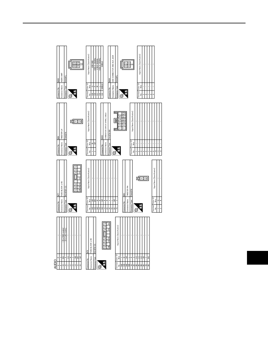
AUDIO SYSTEM
AV-33
< WIRING DIAGRAM >
[AUDIO SYSTEM]
C
D
E
F
G
H
I
J
K
L
M
B
A
O
P
JRNWD1431GB
|
|
|
AV AUDIO SYSTEM AV-33 < WIRING DIAGRAM > [AUDIO SYSTEM] C D E F G H I J K L M B A O P JRNWD1431GB |