Qashqai J11. Wiper & washer - part 5


  Index      Nissan     Qashqai J11. Wiper & washer. Service and Repair Manual


Search            copyright infringement  


Content      ..     3      4      5      6     ..


Qashqai J11. Wiper & washer - part 5


REAR WIPER STOP POSITION SIGNAL CIRCUIT

WW-59

< DTC/CIRCUIT DIAGNOSIS >

C

D

E

F

G

H

I

J

K

M

A

B

WW

N

O

P

REAR WIPER STOP POSITION SIGNAL CIRCUIT

Component Function Check

INFOID:0000000010431004

1.

CHECK REAR WIPER STOP POSITION SIGNAL

CONSULT DATA MONITOR

1.

Select “WIPER” of BCM data monitor item.

2.

Operate the rear wiper.

3.

Check that “RR WIPER STOP” changes to “On” and “Off” linked with the wiper operation.

Is the inspection result normal?

YES

>> Rear wiper stop position signal circuit is normal.

NO

>> Refer to 

WW-59, "Diagnosis Procedure"

.

Diagnosis Procedure

INFOID:0000000010431005

1.

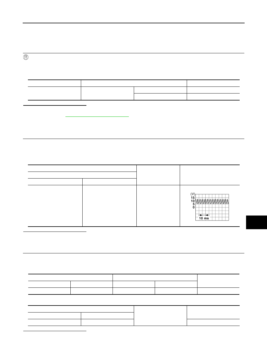
CHECK REAR WIPER MOTOR (AUTO STOP) OUTPUT VOLTAGE

1.

Turn ignition switch OFF.

2.

Disconnect rear wiper motor connector.

3.

Turn ignition switch ON.

4.

Check voltage between rear wiper motor harness connector and ground.

Is the inspection result normal?

YES

>> Replace rear wiper motor.

NO

>> GO TO 2.

2.

CHECK REAR WIPER MOTOR (AUTO STOP) CIRCUIT

1.

Turn ignition switch OFF.

2.

Disconnect BCM connector.

3.

Check continuity between BCM harness connector and rear wiper motor harness connector.

4.

Check continuity between rear wiper motor harness connector and ground.

Is the inspection result normal?

Monitor item

Condition

Monitor status

RR WIPER STOP

Rear wiper motor

Stop position

Off

Except stop position

On

(+)

(

)

Voltage

Rear wiper motor

Connector

Terminal

D84

2

Ground

JMMIA1654GB

BCM 

Rear wiper motor

Continuity

Connector

Terminal

Connector

Terminal

B4

15

D84

2

Existed

Rear wiper motor

Ground

Continuity

Connector

Terminal

D84

2

Not existed

WW-60

< DTC/CIRCUIT DIAGNOSIS >

REAR WIPER STOP POSITION SIGNAL CIRCUIT

YES

>> Replace BCM. Refer to 

BCS-132, "Removal and Installation"

.

NO

>> Repair or replace harness.

HEADLAMP WASHER SWITCH

WW-61

< DTC/CIRCUIT DIAGNOSIS >

C

D

E

F

G

H

I

J

K

M

A

B

WW

N

O

P

HEADLAMP WASHER SWITCH

Component Function Check

INFOID:0000000010721596

1.

CHECK HEADLAMP WASHER SWITCH SIGNAL

CONSULT DATA MONITOR

1.

Turn ignition switch ON.

2.

Select “H/L WSR SW” of BCM (WIPER) data monitor item.

3.

With operating the headlamp washer switch, check the monitor status.

Is the item status normal?

YES

>> Headlamp washer switch circuit is normal.

NO

>> Refer to 

WW-61, "Diagnosis Procedure"

.

Diagnosis Procedure

INFOID:0000000010721597

1.

CHECK HEADLAMP WASHER SWITCH SIGNAL INPUT

1.

Turn ignition switch OFF.

2.

Disconnect headlamp washer switch connector.

3.

Turn ignition switch ON.

4.

Check voltage between headlamp washer switch harness connector and ground.

Is the inspection result normal?

YES

>> GO TO 2.

NO

>> GO TO 3.

2.

CHECK HEADLAMP WASHER SWITCH GROUND CIRCUIT

1.

Turn ignition switch OFF.

2.

Check continuity between headlamp washer switch harness connector and ground.

Is the inspection result normal?

YES

>> Replace headlamp washer switch.

NO

>> Repair or replace harnesses.

3.

CHECK HEADLAMP WASHER SWITCH SIGNAL CIRCUIT

1.

Turn ignition switch OFF.

2.

Disconnect BCM connector.

3.

Check continuity between headlamp washer switch harness connector and BCM harness connector.

4.

Check continuity between headlamp washer switch harness connector and ground.

Monitor item

Condition

Monitor status

H/L WSR SW

Headlamp washer switch

While pressing

On

While not pressing

Off

(+)

(

)

Voltage

Headlamp washer switch

Connector

Terminal

M63

1

Ground

9 – 16 V

Headlamp washer switch

Continuity

Connector

Terminal

M63

2

Ground

Existed

Headlamp washer switch

BCM

Continuity

Connector

Terminal

Connector

Terminal

M63

1

M70

60

Existed

WW-62

< DTC/CIRCUIT DIAGNOSIS >

HEADLAMP WASHER SWITCH

Is the inspection result normal?

YES

>> Replace BCM. Refer to 

BCS-132, "Removal and Installation"

.

NO

>> Repair or replace harnesses.

Headlamp washer switch

Continuity

Connector

Terminal

M63

1

Ground

Not existed

HEADLAMP WASHER CIRCUIT

WW-63

< DTC/CIRCUIT DIAGNOSIS >

C

D

E

F

G

H

I

J

K

M

A

B

WW

N

O

P

HEADLAMP WASHER CIRCUIT

Component Function Check

INFOID:0000000010430984

1.

CHECK HEADLAMP WASHER OPERATION

CONSULT ACTIVE TEST

1.

Select “HEADLAMP WASHER” of IPDM E/R active test item.

2.

With operating the test item, check headlamp operation.

Is the inspection result normal?

YES

>> Headlamp washer circuit is normal.

NO

>> Refer to 

WW-63, "Diagnosis Procedure"

.

Diagnosis Procedure

INFOID:0000000010430985

1.

CHECK HEADLAMP WASHER FUSIBLE LINK

1.

Turn ignition switch OFF.

2.

Check that the following fusible link is not fusing.

Is the inspection result normal?

YES

>> GO TO 2.

NO

>> Replace the fusible link after repairing the applicable circuit.

2.

CHECK HEADLAMP WASHER RELAY POWER SUPPLY

1.

Remove headlamp washer relay.

2.

Check voltage between headlamp washer relay harness connector and ground.

Is the inspection result normal?

YES

>> GO TO 3.

NO

>> Repair or replace harness.

3.

CHECK HEADLAMP WASHER RELAY

Check headlamp washer relay. Refer to 

WW-65, "Component Inspection"

.

Is the inspection result normal?

YES

>> GO TO 4.

NO

>> Replace headlamp washer relay.

4.

CHECK HEADLAMP WASHER RELAY CONTROL SIGNAL

CONSULT ACTIVE TEST

1.

Install headlamp washer relay.

2.

Turn ignition switch ON.

3.

Select “HEADLAMP WASHER” of IPDM E/R active test item.

4.

With operating the test item, check voltage between IPDM E/R harness connector and ground.

On

:Headlamp washer ON operation

Off

:Stop the headlamp washer.

Unit

Fusible link No.

Capacity

Headlamp washer

I

30 A

(+)

(

)

Voltage (Approx.)

Headlamp washer relay

Connector

Terminal

E35

1

Ground

Battery voltage

3

WW-64

< DTC/CIRCUIT DIAGNOSIS >

HEADLAMP WASHER CIRCUIT

Is the inspection result normal?

YES

>> GO TO 7.

NO-1

>> Fixed at 0 

 1 V and remains unchanged: GO TO 5.

NO-2

>> Fixed at 9 

 16 V and remains unchanged: Replace IPDM E/R. Refer to 

PCS-67, "Removal and

Installation"

.

5.

CHECK HEADLAMP WASHER RELAY CONTROL SIGNAL OPEN CIRCUIT

1.

Turn ignition switch OFF.

2.

Remove headlamp washer relay.

3.

Disconnect IPDM E/R harness connector.

4.

Check continuity between IPDM E/R harness connector and headlamp washer relay harness connector.

Is the inspection result normal?

YES

>> GO TO 6.

NO

>> Repair or replace harness.

6.

CHECK HEADLAMP WASHER RELAY CONTROL SIGNAL SHORT CIRCUIT

Check continuity between IPDM E/R harness connector and ground.

Is the inspection result normal?

YES

>> Replace IPDM E/R. Refer to 

PCS-67, "Removal and Installation"

.

NO

>> Repair or replace harness.

7.

CHECK HEADLAMP WASHER PUMP OPEN CIRCUIT

1.

Turn ignition switch OFF.

2.

Remove headlamp washer relay.

3.

Disconnect headlamp washer pump connector.

4.

Check continuity between headlamp washer relay harness connector and headlamp washer pump har-
ness connector.

Is the inspection result normal?

YES

>> GO TO 8.

NO

>> Repair or replace harness.

8.

CHECK HEADLAMP WASHER PUMP (GND) OPEN CIRCUIT

Check continuity between headlamp washer pump harness connector and ground.

(+)

(

)

Condition

Voltage

IPDM E/R

Connector

Terminal

E37

7

Ground

HEAD LAMP WASHER

On

 1 V

Off

 16 V

IPDM E/R

Headlamp washer relay

Continuity

Connector

Terminal

Connector

Terminal

E37

7

E35

2

Existed

IPDM E/R

Ground

Continuity

Connector

Terminal

E37

7

Not existed

Headlamp washer relay

Headlamp washer pump

Continuity

Connector

Terminal

Connector

Terminal

E35

5

E62

1

Existed

HEADLAMP WASHER CIRCUIT

WW-65

< DTC/CIRCUIT DIAGNOSIS >

C

D

E

F

G

H

I

J

K

M

A

B

WW

N

O

P

Is the inspection result normal?

YES

>> Replace headlamp washer pump.

NO

>> Repair or replace harness.

Component Inspection

INFOID:0000000010430986

1.

CHECK HEADLAMP WASHER RELAY

1.

Turn ignition switch OFF.

2.

Remove headlamp washer relay.

3.

Check continuity of headlamp washer relay.

Is the inspection result normal?

YES

>> Headlamp washer relay is normal.

NO

>> Replace headlamp washer relay.

Headlamp washer pump

Ground

Continuity

Connector

Terminal

E62

2

Existed

Headlamp washer relay

Condition

Continuity

Terminal

3

5

12 V direct current supply between terminals 1 and 2.

Existed

Not Apply

Not existed

WW-66

< SYMPTOM DIAGNOSIS >

WIPER AND WASHER SYSTEM SYMPTOMS

SYMPTOM DIAGNOSIS

WIPER AND WASHER SYSTEM SYMPTOMS

WITH LIGHT & RAIN SENSOR

WITH LIGHT & RAIN SENSOR : Symptom Table

INFOID:0000000010430987

NOTE:
Perform the self-diagnosis with CONSULT before the symptom diagnosis. Perform the trouble diagnosis if any
DTC is detected.

Symptom

Probable malfunction location

Inspection item

Front wiper does not 
operate

HI only

• Combination switch
• Harness between combination switch and BCM
• BCM

Combination switch 
Refer to 

BCS-130, "Symp-

tom Table"

.

• IPDM E/R
• Harness between IPDM E/R and front wiper 

motor

• Front wiper motor

Front wiper motor (HI) circuit
Refer to 

WW-49, "Compo-

nent Function Check"

.

Front wiper request signal
• BCM
• IPDM E/R

IPDM E/R DATA MONITOR
“FR WIP REQ”

LO only

• Combination switch
• Harness between combination switch and BCM
• BCM

Combination switch
Refer to 

BCS-130, "Symp-

tom Table"

.

• IPDM E/R
• Harness between IPDM E/R and front wiper 

motor

• Front wiper motor

Front wiper motor (LO) circuit
Refer to 

WW-47, "Compo-

nent Function Check"

.

Front wiper request signal
• BCM
• IPDM E/R

IPDM E/R DATA MONITOR
“FR WIP REQ”

AUTO only

• Combination switch
• Harness between combination switch and BCM
• BCM

Combination switch
Refer to 

BCS-130, "Symp-

tom Table"

.

• Light & rain sensor
• Harness between light & rain sensor and BCM
• BCM

Light & rain sensor
Refer to 

WW-54, "Compo-

nent Function Check"

.

HI, LO and AUTO

SYMPTOM DIAGNOSIS
“FRONT WIPER DOES NOT OPERATE”
Refer to 

WW-73, "Diagnosis Procedure"

.

WIPER AND WASHER SYSTEM SYMPTOMS

WW-67

< SYMPTOM DIAGNOSIS >

C

D

E

F

G

H

I

J

K

M

A

B

WW

N

O

P

Front wiper does not 
stop

HI only

• Combination switch
• BCM

Combination switch
Refer to 

BCS-130, "Symp-

tom Table"

.

Front wiper request signal
• BCM
• IPDM E/R

IPDM E/R DATA MONITOR
“FR WIP REQ”

IPDM E/R

LO only

• Combination switch
• BCM

Combination switch
Refer to 

BCS-130, "Symp-

tom Table"

.

Front wiper request signal
• BCM
• IPDM E/R

IPDM E/R DATA MONITOR
“FR WIP REQ”

IPDM E/R

AUTO only

• Combination switch
• BCM

Combination switch
Refer to 

BCS-130, "Symp-

tom Table"

.

• Light & rain sensor
• Harness between light & rain sensor and BCM
• BCM

Light & rain sensor
Refer to 

WW-54, "Compo-

nent Function Check"

.

Front wiper does not 
operate normally

Sensitivity adjustment 
cannot be performed.

• Combination switch
• Harness between combination switch and BCM
• BCM

Combination switch
Refer to 

BCS-130, "Symp-

tom Table"

.

BCM

Auto wiping operation 
does not operate

Check that the wiper setting is auto wiping operation
Refer to 

WW-23, "WIPER : CONSULT Function - WIPER"

.

Wiper is not linked to 
the washer operation.

• Combination switch
• Harness between combination switch and BCM
• BCM

Combination switch
Refer to 

BCS-130, "Symp-

tom Table"

.

BCM

Does not return to stop 
position. [Repeatedly 
operates for 10 sec-
onds and then stops 
for 20 seconds. (Fail-
safe)]

• IPDM E/R
• Harness between IPDM E/R and front wiper 

motor

• Front wiper motor

Front wiper stop position sig-
nal circuit
Refer to 

WW-51, "Compo-

nent Function Check"

.

Rear wiper does not 
operate

ON only

• Combination switch
• Harness between combination switch and BCM
• BCM

Combination switch 
Refer to 

BCS-130, "Symp-

tom Table"

.

INT only

• Combination switch
• Harness between combination switch and BCM
• BCM

Combination switch 
Refer to 

BCS-130, "Symp-

tom Table"

.

ON and INT

• Combination switch
• Harness between combination switch and BCM
• BCM

Combination switch 
Refer to 

BCS-130, "Symp-

tom Table"

.

• BCM
• Harness between rear wiper motor and BCM
• Harness between rear wiper motor and ground
• Rear wiper motor

Rear wiper motor circuit
Refer to 

WW-58, "Diagnosis 

Procedure"

.

Rear wiper does not 
stop

ON only

• Combination switch
• BCM

Combination switch 
Refer to 

BCS-130, "Symp-

tom Table"

.

INT only

• Combination switch
• BCM

Combination switch 
Refer to 

BCS-130, "Symp-

tom Table"

.

Symptom

Probable malfunction location

Inspection item

WW-68

< SYMPTOM DIAGNOSIS >

WIPER AND WASHER SYSTEM SYMPTOMS

WITHOUT LIGHT & RAIN SENSOR

WITHOUT LIGHT & RAIN SENSOR : Symptom Table

INFOID:0000000010430988

NOTE:
Perform the self-diagnosis with CONSULT before the symptom diagnosis. Perform the trouble diagnosis if any
DTC is detected.

Rear wiper does not 
operate normally

Wiper is not linked to 
the washer operation

• Combination switch
• Harness between rear wiper motor and BCM
• BCM

Combination switch 
Refer to 

BCS-130, "Symp-

tom Table"

.

BCM

Rear wiper does not 
return to the stop posi-
tion. [Stops after a five-
second operation. 
(Fail-safe)]

• BCM
• Harness between rear wiper motor and BCM
• Rear wiper motor

Rear wiper stop position sig-
nal circuit
Refer to 

WW-59, "Compo-

nent Function Check"

.

Rear wiper does not 
operate even when 
shift position is “R”.

Reverse switch signal (CAN communication)
• BCM
• IPDM E/R

BCM DATA MONITOR
“REVERSE SIGNAL - IPDM”

Headlamp washer 
does not operate.

Headlamp washer 
does not operate when 
headlamps are turned 
ON.

• Harness between headlamp washer switch and 

BCM

• Harness between headlamp washer switch and 

ground

• Headlamp washer switch
• BCM

Headlamp washer switch
Refer to 

WW-61, "Compo-

nent Function Check"

.

• Combination switch
• Harness between combination switch and BCM
• BCM

Combination switch
Refer to 

BCS-130, "Symp-

tom Table"

.

• Fusible link
• Harness between fusible link and headlamp 

washer relay

• Headlamp washer relay
• Harness between headlamp washer relay and 

IPDM E/R

• IPDM E/R
• Harness between headlamp washer relay and 

headlamp washer pump

• Harness between headlamp washer pump and 

ground

• Headlamp washer pump

Headlamp washer circuit
Refer to 

WW-63, "Compo-

nent Function Check"

.

BCM

Symptom

Probable malfunction location

Inspection item

WIPER AND WASHER SYSTEM SYMPTOMS

WW-69

< SYMPTOM DIAGNOSIS >

C

D

E

F

G

H

I

J

K

M

A

B

WW

N

O

P

Symptom

Probable malfunction location

Inspection item

Front wiper does not 
operate

HI only

• Combination switch
• Harness between combination switch and BCM
• BCM

Combination switch 
Refer to 

BCS-130, "Symp-

tom Table"

.

• IPDM E/R
• Harness between IPDM E/R and front wiper 

motor

• Front wiper motor

Front wiper motor (HI) circuit
Refer to 

WW-49, "Compo-

nent Function Check"

.

Front wiper request signal
• BCM
• IPDM E/R

IPDM E/R
Data monitor “FR WIP REQ”

LO and INT

• IPDM E/R
• Harness between IPDM E/R and front wiper 

motor

• Front wiper motor

Front wiper motor (LO) circuit
Refer to 

WW-47, "Compo-

nent Function Check"

.

LO only

• Combination switch
• Harness between combination switch and BCM
• BCM

Combination switch 
Refer to 

BCS-130, "Symp-

tom Table"

.

Front wiper request signal
• BCM
• IPDM E/R

IPDM E/R
Data monitor “FR WIP REQ”

INT only

• Combination switch
• Harness between combination switch and BCM
• BCM

Combination switch 
Refer to 

BCS-130, "Symp-

tom Table"

.

Front wiper request signal
• BCM
• IPDM E/R

IPDM E/R
Data monitor “FR WIP REQ”

HI, LO and INT

SYMPTOM DIAGNOSIS
Refer to 

WW-73, "Diagnosis Procedure"

.

Front wiper does not 
stop

HI only

• Combination switch
• BCM

Combination switch 
Refer to 

BCS-130, "Symp-

tom Table"

.

Front wiper request signal
• BCM
• IPDM E/R

IPDM E/R
Data monitor “FR WIP REQ”

IPDM E/R

LO only

• Combination switch
• BCM

Combination switch 
Refer to 

BCS-130, "Symp-

tom Table"

.

Front wiper request signal
• BCM
• IPDM E/R

IPDM E/R
Data monitor “FR WIP REQ”

IPDM E/R

INT only

• Combination switch
• BCM

Combination switch 
Refer to 

BCS-130, "Symp-

tom Table"

.

Front wiper request signal
• BCM
• IPDM E/R

IPDM E/R
Data monitor “FR WIP REQ”

W W - 7 0

< SYMPTOM DIAGNOSIS >

WIPER AND WASHER SYSTEM SYMPTOMS

Front wiper does not 
operate normally

Intermittent adjust-
ment cannot be per-
formed

• Combination switch
• Harness between combination switch and BCM
• BCM

Combination switch 
Refer to 

BCS-130, "Symp-

tom Table"

.

BCM

Intermittent control 
linked with vehicle 
speed cannot be per-
formed

Check the wiper setting is linked with vehicle speed.
Refer to 

WW-23, "WIPER : CONSULT Function - WIPER"

.

Wiper is not linked to 
the washer operation

• Combination switch
• Harness between combination switch and BCM
• BCM

Combination switch 
Refer to 

BCS-130, "Symp-

tom Table"

.

BCM

Does not return to 
stop position [Re-
peatedly operates for 
10 seconds and then 
stops for 20 seconds. 
After that, it stops the 
operation. (Fail-
safe)]

• IPDM  E/R
• Harness between IPDM E/R and front wiper 

motor

• Front wiper motor

Front wiper stop position sig-
nal circuit
Refer to 

WW-51, "Compo-

nent Function Check"

.

Rear wiper does not 
operate

ON only

• Combination switch
• Harness between combination switch and BCM
• BCM

Combination switch 
Refer to 

BCS-130, "Symp-

tom Table"

.

INT only

• Combination switch
• Harness between combination switch and BCM
• BCM

Combination switch 
Refer to 

BCS-130, "Symp-

tom Table"

.

ON and INT

• Combination switch
• Harness between combination switch and BCM
• BCM

Combination switch 
Refer to 

BCS-130, "Symp-

tom Table"

.

• BCM
• Harness between rear wiper motor and BCM
• Harness between rear wiper motor and ground
• Rear wiper motor

Rear wiper motor circuit
Refer to 

WW-58, "Diagnosis 

Procedure"

.

Rear wiper does not 
stop

ON only

• Combination switch
• BCM

Combination switch 
Refer to 

BCS-130, "Symp-

tom Table"

.

INT only

• Combination switch
• BCM

Combination switch 
Refer to 

BCS-130, "Symp-

tom Table"

.

Rear wiper does not 
operate normally

Wiper is not linked to 
the washer operation

• Combination switch
• Harness between rear wiper motor and BCM
• BCM

Combination switch 
Refer to 

BCS-130, "Symp-

tom Table"

.

BCM

Rear wiper does not 
return to the stop po-
sition. [Stops after a 
five-second opera-
tion. (Fail-safe)]

• BCM
• Harness between rear wiper motor and BCM
• Rear wiper motor

Rear wiper stop position sig-
nal circuit
Refer to 

WW-59, "Compo-

nent Function Check"

.

Rear wiper does not 
operate even when 
shift position is “R”.

Reverse switch signal (CAN communication)
• BCM
• IPDM  E/R

BCM DATA MONITOR
“REVERSE SIGNAL - IPDM”

Symptom

Probable malfunction location

Inspection item

WIPER AND WASHER SYSTEM SYMPTOMS

WW-71

< SYMPTOM DIAGNOSIS >

C

D

E

F

G

H

I

J

K

M

A

B

WW

N

O

P

Headlamp washer 
does not operate.

Headlamp washer 
does not operate 
when headlamps are 
turned ON.

• Harness between headlamp washer switch and 

BCM

• Harness between headlamp washer switch and 

ground

• Headlamp washer switch
• BCM

Headlamp washer switch
Refer to 

WW-61, "Compo-

nent Function Check"

.

• Combination switch
• Harness between combination switch and BCM
• BCM

Combination switch
Refer to 

BCS-130, "Symp-

tom Table"

.

• Fusible link
• Harness between fusible link and headlamp 

washer relay

• Headlamp washer relay
• Harness between headlamp washer relay and 

IPDM E/R

• IPDM E/R
• Harness between headlamp washer relay and 

headlamp washer pump

• Harness between headlamp washer pump and 

ground

• Headlamp washer pump

Headlamp washer circuit
Refer to 

WW-63, "Compo-

nent Function Check"

.

BCM

Symptom

Probable malfunction location

Inspection item

WW-72

< SYMPTOM DIAGNOSIS >

NORMAL OPERATING CONDITION

NORMAL OPERATING CONDITION

Description

INFOID:0000000010430989

FRONT WIPER MOTOR PROTECTION FUNCTION

• IPDM E/R may stop the front wiper to protect the front wiper motor if any obstruction (operation resistance)

such as a large amount of snow is detected during the front wiper operation.

• At that time turn OFF the front wiper and remove the foreign object. Then reactivate the front wiper. The

wiper will operate normally.

REAR WIPER MOTOR PROTECTION FUNCTION

• BCM may stop rear wiper to protect the rear wiper motor when the rear wiper is stopped for 5 seconds or

more due to a snowfall.

• Rear wiper operates normally 1 minute after the obstacles are removed with rear wiper OFF.

FRONT WIPER DOES NOT OPERATE

WW-73

< SYMPTOM DIAGNOSIS >

C

D

E

F

G

H

I

J

K

M

A

B

WW

N

O

P

FRONT WIPER DOES NOT OPERATE

Description

INFOID:0000000010430990

The front wiper does not operate under any operation conditions.

Diagnosis Procedure

INFOID:0000000010430991

1.

CHECK WIPER RELAY OPERATION

CONSULT ACTIVE TEST

1.

Select “FRONT WIPER” of IPDM E/R active test item.

2.

With operating the test item, check front wiper operation.

Is front wiper operation normally?

YES

>> GO TO 4.

NO

>> GO TO 2.

2.

CHECK FRONT WIPER MOTOR FUSE

1.

Turn ignition switch OFF.

2.

Check that the following fuse is not fusing.

Is the inspection result normal?

YES

>> GO TO 3.

NO

>> Replace the fuse after repairing the applicable circuit.

3.

CHECK FRONT WIPER MOTOR GROUND CIRCUIT 

Check front wiper motor ground circuit. Refer to 

WW-53, "Diagnosis Procedure"

.

Is the inspection result normal?

YES

>> GO TO 4.

NO

>> Repair or replace harness.

4.

CHECK FRONT WIPER REQUEST SIGNAL INPUT

CONSULT DATA MONITOR

1.

Select “FR WIP REQ” of IPDM E/R data monitor item.

2.

Switch the front wiper switch to HI and LO.

3.

With operating the front wiper switch, check the status of “FR WIP REQ”.

Is the inspection result normal?

YES

>> Replace IPDM E/R. Refer to 

PCS-67, "Removal and Installation"

.

NO

>> GO TO 5.

5.

CHECK COMBINATION SWITCH

Perform the inspection of the combination switch. Refer to 

BCS-130, "Symptom Table"

.

Is combination switch normal?

LOW

: Front wiper LO operation

HIGH

: Front wiper HI operation

OFF

: Stop the front wiper.

Unit

Location

No.

Capacity

Front wiper motor

IPDM E/R

60

30 A

Monitor item

Condition

Monitor status

FR WIP REQ

Front wiper switch

HI

HIGH

LO

LOW

INT

OFF

STOP

WW-74

< SYMPTOM DIAGNOSIS >

FRONT WIPER DOES NOT OPERATE

YES

>> Replace BCM. Refer to 

BCS-132, "Removal and Installation"

.

NO

>> Repair or replace the applicable parts.


Content      ..     3      4      5      6     ..