Qashqai J11. Wiper & washer - part 4


  Index      Nissan     Qashqai J11. Wiper & washer. Service and Repair Manual


Search            copyright infringement  


Content      ..     2      3      4      5     ..


Qashqai J11. Wiper & washer - part 4


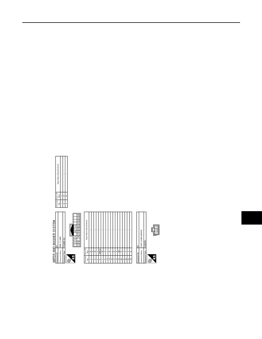
WIPER AND WASHER SYSTEM

WW-43

< WIRING DIAGRAM >

C

D

E

F

G

H

I

J

K

M

A

B

WW

N

O

P

JRLWD2259GB

WW-44

< BASIC INSPECTION >

DIAGNOSIS AND REPAIR WORK FLOW

BASIC INSPECTION

DIAGNOSIS AND REPAIR WORK FLOW

Work Flow

INFOID:0000000010430973

OVERALL SEQUENCE

DETAILED FLOW

JMKIA8652GB

DIAGNOSIS AND REPAIR WORK FLOW

WW-45

< BASIC INSPECTION >

C

D

E

F

G

H

I

J

K

M

A

B

WW

N

O

P

1.

GET INFORMATION FOR SYMPTOM

1.

Get detailed information from the customer about the symptom (the condition and the environment when
the incident/malfunction occurs).

2.

Check operation condition of the function that is malfunctioning.

>> GO TO 2.

2.

CHECK DTC

1.

Check DTC.

2.

Perform the following procedure if DTC is detected.

-

Record DTC and freeze frame data (Print them out using CONSULT.)

-

Erase DTC.

-

Study the relationship between the cause detected by DTC and the symptom described by the customer.

3.

Check related service bulletins for information.

Are any symptoms described and any DTC detected?

Symptom is described, DTC is detected>>GO TO 3.
Symptom is described, DTC is not detected>>GO TO 4.
Symptom is not described, DTC is detected>>GO TO 5.

3.

CONFIRM THE SYMPTOM

Try to confirm the symptom described by the customer.
Also study the normal operation and fail-safe related to the symptom.
Verify relation between the symptom and the condition when the symptom is detected.

>> GO TO 5.

4.

CONFIRM THE SYMPTOM

Try to confirm the symptom described by the customer.
Verify relation between the symptom and the condition when the symptom is detected.

>> GO TO 6.

5.

PERFORM DTC CONFIRMATION PROCEDURE

Perform DTC CONFIRMATION PROCEDURE for the detected DTC, and then check that DTC is detected
again. At this time, always connect CONSULT to the vehicle, and check self diagnostic results in real time.
If two or more DTCs are detected, refer to DTC INSPECTION PRIORITY CHART, and determine trouble diag-
nosis order.
NOTE:
• Freeze frame data is useful if the DTC is not detected.
• Perform Component Function Check if DTC CONFIRMATION PROCEDURE is not included on Service

Manual. This simplified check procedure is an effective alternative though DTC cannot be detected during
this check.
If the result of Component Function Check is NG, it is the same as the detection of DTC by DTC CONFIR-
MATION PROCEDURE.

Is DTC detected?

YES

>> GO TO 7.

NO

>> Check according to 

GI-41, "Intermittent Incident"

.

6.

DETECT MALFUNCTIONING SYSTEM BY SYMPTOM DIAGNOSIS

Detect malfunctioning system according to SYMPTOM DIAGNOSIS based on the confirmed symptom in step
4, and determine the trouble diagnosis order based on possible causes and symptom.

Is the symptom described?

YES

>> GO TO 7.

NO

>> Monitor input data from related sensors or check voltage of related module terminals using CON-

SULT.

7.

DETECT MALFUNCTIONING PART BY DIAGNOSIS PROCEDURE

WW-46

< BASIC INSPECTION >

DIAGNOSIS AND REPAIR WORK FLOW

Inspect according to Diagnosis Procedure of the system.

Is malfunctioning part detected?

YES

>> GO TO 8.

NO

>> Check according to 

GI-41, "Intermittent Incident"

.

8.

REPAIR OR REPLACE THE MALFUNCTIONING PART

1.

Repair or replace the malfunctioning part.

2.

Reconnect parts or connectors disconnected during Diagnosis Procedure again after repair and replace-
ment.

3.

Check DTC. If DTC is detected, erase it.

>> GO TO 9.

9.

FINAL CHECK

When DTC is detected in step 2, perform DTC CONFIRMATION PROCEDURE again, and then check that the
malfunction is repaired securely.
When symptom is described by the customer, refer to confirmed symptom in step 3 or 4, and check that the
symptom is not detected.

Is DTC detected and does symptom remain?

YES-1 >> DTC is detected: GO TO 7.
YES-2 >> Symptom remains: GO TO 4.
NO

>> Before returning the vehicle to the customer, always erase DTC.

FRONT WIPER MOTOR LO CIRCUIT

WW-47

< DTC/CIRCUIT DIAGNOSIS >

C

D

E

F

G

H

I

J

K

M

A

B

WW

N

O

P

DTC/CIRCUIT DIAGNOSIS

FRONT WIPER MOTOR LO CIRCUIT

Component Function Check

INFOID:0000000010430974

1.

CHECK FRONT WIPER LO OPERATION

CONSULT ACTIVE TEST

1.

Select “FRONT WIPER” of IPDM E/R active test item.

2.

With operating the test item, check front wiper operation.

Is the inspection result normal?

YES

>> Front wiper motor LO circuit is normal.

NO

>> Refer to 

WW-47, "Diagnosis Procedure"

.

Diagnosis Procedure

INFOID:0000000010430975

1.

CHECK FRONT WIPER MOTOR (LO) OUTPUT VOLTAGE

1.

Turn ignition switch OFF.

2.

Disconnect front wiper motor connector.

3.

Turn ignition switch ON.

4.

Turn front wiper switch to LOW, and wait for 10 seconds.

5.

Check voltage between front wiper motor harness connector and ground.

LHD

RHD

*: According to front wiper protection function, IPDM E/R supplies voltage for 10 seconds (9 

 16 V) and then

stops for 20 seconds (0 

 1 V). This operation occurs repeatedly.

Is the inspection result normal?

YES

>> Replace front wiper motor.

NO

>> GO TO 2.

2.

CHECK FRONT WIPER MOTOR (LO) CIRCUIT

1.

Turn ignition switch OFF.

2.

Disconnect IPDM E/R connector.

3.

Check continuity between IPDM E/R harness connector and front wiper motor harness connector.

LHD

Lo

: Front wiper (LO) operation

Off

: Stop the front wiper.

(+)

(

)

Voltage

Front wiper motor

Connector

Terminal

E19

2

Ground

 16 V

(10 seconds*)

(+)

(

)

Voltage

Front wiper motor

Connector

Terminal

E63

2

Ground

 16 V

(10 seconds*)

IPDM E/R

Front wiper motor

Continuity

Connector

Terminal

Connector

Terminal

E39

46

E19

2

Existed

WW-48

< DTC/CIRCUIT DIAGNOSIS >

FRONT WIPER MOTOR LO CIRCUIT

RHD

4.

Check continuity between IPDM E/R harness connector and ground.

Is the inspection result normal?

YES

>> Replace IPDM E/R. Refer to 

PCS-67, "Removal and Installation"

.

NO

>> Repair or replace harness.

IPDM E/R

Front wiper motor

Continuity

Connector

Terminal

Connector

Terminal

E39

46

E63

2

Existed

IPDM E/R

Ground

Continuity

Connector

Terminal

E39

46

Not existed

FRONT WIPER MOTOR HI CIRCUIT

WW-49

< DTC/CIRCUIT DIAGNOSIS >

C

D

E

F

G

H

I

J

K

M

A

B

WW

N

O

P

FRONT WIPER MOTOR HI CIRCUIT

Component Function Check

INFOID:0000000010430976

1.

CHECK FRONT WIPER HI OPERATION

CONSULT ACTIVE TEST

1.

Select “FRONT WIPER” of IPDM E/R active test item.

2.

With operating the test item, check front wiper operation.

Is the inspection result normal?

YES

>> Front wiper motor HI circuit is normal.

NO

>> Refer to 

WW-49, "Diagnosis Procedure"

.

Diagnosis Procedure

INFOID:0000000010430977

1.

CHECK FRONT WIPER MOTOR (HI) OUTPUT VOLTAGE

CONSULT ACTIVE TEST

1.

Turn ignition switch OFF.

2.

Disconnect front wiper motor connector.

3.

Turn ignition switch ON.

4.

Select “FRONT WIPER” of IPDM E/R active test item.

5.

With operating the test item, check voltage between front wiper motor harness connector and ground.

LHD

RHD

*: According to front wiper protection function, IPDM E/R supplies voltage for 10 seconds (9 

 16 V) and then

stops for 20 seconds (0 

 1 V). This operation occurs repeatedly.

Is the inspection result normal?

YES

>> Replace front wiper motor.

NO

>> GO TO 2.

2.

CHECK FRONT WIPER MOTOR (HI) CIRCUIT

1.

Turn ignition switch OFF.

2.

Disconnect IPDM E/R connector.

3.

Check continuity between IPDM E/R harness connector and front wiper motor harness connector.

LHD

Hi

: Front wiper (HI) operation

Off

: Stop the front wiper.

(+)

(

)

Condition

Voltage

Front wiper motor

Connector

Terminal

E19

1

Ground

FRONT WIPER

Hi

 16 V

(10 seconds*)

(+)

(

)

Condition

Voltage

Front wiper motor

Connector

Terminal

E63

1

Ground

FRONT WIPER

Hi

 16 V

(10 seconds*)

IPDM E/R

Front wiper motor

Continuity

Connector

Terminal

Connector

Terminal

E39

43

E19

1

Existed

WW-50

< DTC/CIRCUIT DIAGNOSIS >

FRONT WIPER MOTOR HI CIRCUIT

RHD

4.

Check continuity between IPDM E/R harness connector and ground.

Is the inspection result normal?

YES

>> Replace IPDM E/R. Refer to 

PCS-67, "Removal and Installation"

.

NO

>> Repair or replace harness.

IPDM E/R

Front wiper motor

Continuity

Connector

Terminal

Connector

Terminal

E39

43

E63

1

Existed

IPDM E/R

Ground

Continuity

Connector

Terminal

E39

43

Not existed

FRONT WIPER STOP POSITION SIGNAL CIRCUIT

WW-51

< DTC/CIRCUIT DIAGNOSIS >

C

D

E

F

G

H

I

J

K

M

A

B

WW

N

O

P

FRONT WIPER STOP POSITION SIGNAL CIRCUIT

Component Function Check

INFOID:0000000010430978

1.

CHECK FRONT WIPER STOP POSITION SIGNAL

CONSULT DATA MONITOR

1.

Select “FR WIPER STOP POSITION” of IPDM E/R data monitor item.

2.

Operate the front wiper.

3.

With the front wiper operation, check the monitor status.

Is the inspection result normal?

YES

>> Front wiper stop position signal circuit is normal.

NO

>> Refer to 

WW-51, "Diagnosis Procedure"

.

Diagnosis Procedure

INFOID:0000000010430979

1.

CHECK IPDM E/R OUTPUT VOLTAGE

1.

Turn ignition switch OFF.

2.

Disconnect front wiper motor connector.

3.

Turn ignition switch ON.

4.

Check voltage between front wiper motor harness connector and ground.

LHD

RHD

Is the inspection result normal?

YES

>> Replace front wiper motor.

NO

>> GO TO 2.

2.

CHECK FRONT WIPER MOTOR (AUTO STOP) CIRCUIT

1.

Turn ignition switch OFF.

2.

Disconnect IPDM E/R connector.

3.

Check continuity between IPDM E/R harness connector and front wiper motor harness connector.

LHD

RHD

4.

Check continuity between IPDM E/R harness connector and ground.

Monitor item

Condition

Monitor status

FR WIPER STOP POSITION

Front wiper motor

Stop position

STOP P

Except stop position

ACTIVE P

(+)

(

)

Voltage

Front wiper motor

Connector

Terminal

E19

4

Ground

9 - 16 V

(+)

(

)

Voltage

Front wiper motor

Connector

Terminal

E63

4

Ground

9 - 16 V

IPDM E/R 

Front wiper motor

Continuity

Connector

Terminal

Connector

Terminal

E38

33

E19

4

Existed

IPDM E/R 

Front wiper motor

Continuity

Connector

Terminal

Connector

Terminal

E38

33

E63

4

Existed

WW-52

< DTC/CIRCUIT DIAGNOSIS >

FRONT WIPER STOP POSITION SIGNAL CIRCUIT

Is the inspection result normal?

YES

>> Replace IPDM E/R. Refer to 

PCS-67, "Removal and Installation"

.

NO

>> Repair or replace harness.

IPDM E/R

Ground

Continuity

Connector

Terminal

E38

33

Not existed

FRONT WIPER MOTOR GROUND CIRCUIT

WW-53

< DTC/CIRCUIT DIAGNOSIS >

C

D

E

F

G

H

I

J

K

M

A

B

WW

N

O

P

FRONT WIPER MOTOR GROUND CIRCUIT

Diagnosis Procedure

INFOID:0000000010430980

1.

CHECK FRONT WIPER MOTOR GROUND CIRCUIT

1.

Turn ignition switch OFF.

2.

Disconnect front wiper motor connector.

3.

Check continuity between front wiper motor harness connector and ground.

LHD

RHD

Is the inspection result normal?

YES

>> INSPECTION END

NO

>> Repair or replace harness.

Front wiper motor

Ground

Continuity

Connector

Terminal

E19

5

Existed

Front wiper motor

Ground

Continuity

Connector

Terminal

E63

5

Existed

WW-54

< DTC/CIRCUIT DIAGNOSIS >

LIGHT & RAIN SENSOR

LIGHT & RAIN SENSOR

Component Function Check

INFOID:0000000010430981

1.

CHECK FRONT WIPER AUTO OPERATION

1.

Clean rain sensor detection area of windshield fully.

2.

When the front wiper switch is turned to AUTO position, front wiper operates once regardless of a rainy
condition.

Is front wiper (AUTO) operation normally?

YES

>> Rain sensor circuit is normal.

NO

>> Refer to 

WW-54, "Diagnosis Procedure"

.

Diagnosis Procedure

INFOID:0000000010430982

1.

CHECK FUSE

1.

Turn ignition switch OFF.

2.

Check that the following fuse is not fusing.

Is the inspection result normal?

YES

>> GO TO 2.

NO

>> Replace the fuse after repairing the applicable circuit.

2.

CHECK RAIN SENSOR POWER SUPPLY

1.

Disconnect light & rain sensor connector.

2.

Turn ignition switch ON.

3.

Check voltage between rain sensor harness connector and ground.

Is the inspection result normal?

YES

>> GO TO 7.

NO

>> GO TO 3.

3.

CHECK INTERIOR ROOM LAMP RELAY CIRCUIT 1

1.

Turn ignition switch OFF.

2.

Remove interior room lamp relay.

3.

Check voltage between interior room lamp relay harness connector and ground.

Is the inspection result normal?

YES

>> GO TO 4.

NO

>> Repair or replace harnesses.

4.

CHECK INTERIOR ROOM LAMP RELAY

Check interior room lamp relay.
Refer to 

WW-56, "Component Inspection"

.

Fuse No.

Capacity

22

10 A

(+)

(

)

Voltage (Approx.)

Light & rain sensor

Connector

Terminal

R5

1

Ground Battery 

voltage

(+)

(-)

Voltage

Interior room lamp relay

Connector

Terminal

M80

1

Ground

Battery voltage

6

LIGHT & RAIN SENSOR

WW-55

< DTC/CIRCUIT DIAGNOSIS >

C

D

E

F

G

H

I

J

K

M

A

B

WW

N

O

P

Is the inspection result normal?

YES

>> GO TO 5.

NO

>> Repair interior room lamp relay.

5.

CHECK INTERIOR ROOM LAMP RELAY CIRCUIT 2

1.

Disconnect light & rain connector.

2.

Check continuity between interior room lamp relay harness connector and light & rain harness connector.

Is the inspection result normal?

YES

>> GO TO 6.

NO

>> Repair or replace harnesses.

6.

CHECK INTERIOR ROOM LAMP RELAY CIRCUIT 3

1.

Disconnect BCM connector.

2.

Check continuity between interior room lamp relay harness connector and BCM harness connector.

Is the inspection result normal?

YES

>> Replace BCM. Refer to 

BCS-132, "Removal and Installation"

.

NO

>> Repair or replace harnesses.

7.

CHECK LIGHT & RAIN SENSOR GROUND CIRCUIT

1.

Turn ignition switch OFF.

2.

Check continuity between rain sensor harness connector and ground.

Is the inspection result normal?

YES

>> GO TO 8.

NO

>> Repair or replace harness.

8.

CHECK LIGHT & RAIN SENSOR SIGNAL

1.

Connect light & rain sensor connector.

2.

Turn ignition switch ON.

3.

Check voltage between BCM harness connector and ground using oscilloscope.

Is the inspection result normal?

Interior room lamp relay

Light & rain

Continuity

Connector

Terminal

Connector

Terminal

M80

7

R5

1

Existed

Interior room lamp relay

BCM

Continuity

Connector

Terminal

Connector

Terminal

M80

2

M70

44

Existed

Light & rain sensor

Continuity

Connector

Terminal

R5

3

Ground

Existed

(+)

(

)

Condition

Voltage

BCM

Connector

Terminal

M70

47

Ground Ignition 

switch 

ON

Approx. 8.7V

JPMIA0156GB

WW-56

< DTC/CIRCUIT DIAGNOSIS >

LIGHT & RAIN SENSOR

YES

>> Replace light & rain sensor.

NO

>> GO TO 9.

9.

CHECK RAIN SENSOR SIGNAL CIRCUIT

1.

Turn ignition switch OFF.

2.

Disconnect BCM connector and light & rain sensor connector.

3.

Check continuity between BCM harness connector and light & rain sensor harness connector.

4.

Check continuity between BCM harness connector and ground.

Is the inspection result normal?

YES

>> Replace BCM. Refer to 

BCS-132, "Removal and Installation"

.

NO

>> Repair or replace harness.

Component Inspection

INFOID:0000000010503212

1.

CHECK INTERIOR ROOM LAMP RELAY

1.

Turn ignition switch OFF.

2.

Remove interior room lamp relay.

3.

Check continuity between interior room lamp relay terminals.

Is the inspection result normal?

YES

>> INSPECTION END

NO

>> Replace interior room lamp relay.

BCM

Light & rain sensor

Continuity

Connector

Terminal

Connector

Terminal

M70

47

R5

2

Existed

BCM

Continuity

Connector

Terminal

M70

47

Ground

Existed

Interior room lamp relay

Condition

Continuity

Terminal

6

7

12 V direct current supply between terminals 1 and 2.

Existed

No current supply

Not existed

WASHER SWITCH

WW-57

< DTC/CIRCUIT DIAGNOSIS >

C

D

E

F

G

H

I

J

K

M

A

B

WW

N

O

P

WASHER SWITCH

Component Inspection

INFOID:0000000010430983

1.

CHECK WASHER SWITCH

1.

Turn ignition switch OFF.

2.

Disconnect combination switch connector.

3.

Check continuity between the combination switch terminals.

Is the inspection result normal?

YES

>> INSPECTION END

NO

>> Replace combination switch.

Combination switch

Condition

Continuity

Terminal

11

16

Front washer switch ON

Existed

14

9

11

14

Rear washer switch ON

16

9

WW-58

< DTC/CIRCUIT DIAGNOSIS >

REAR WIPER MOTOR CIRCUIT

REAR WIPER MOTOR CIRCUIT

Diagnosis Procedure

INFOID:0000000010431003

1.

CHECK REAR WIPER MOTOR OUTPUT VOLTAGE

1.

Turn rear wiper switch OFF, and wait for 1 minute or more. 

2.

Turn ignition switch OFF.

3.

Disconnect rear wiper motor connector.

4.

Turn ignition switch ON.

5.

With operating rear wiper switch, check voltage between rear wiper motor harness connector and ground.

*: When rear wiper motor connector is disconnected and rear wiper switch is ON for more than 5 seconds,
BCM stops the power supply according to rear wiper motor protection function. To perform the check again,
turn rear wiper switch OFF, wait for 1 minute or more, and then perform the check.

Is the inspection result normal?

YES

>> GO TO 3.

NO

>> GO TO 2.

2.

CHECK REAR WIPER MOTOR CIRCUIT

1.

Turn ignition switch OFF.

2.

Disconnect BCM connector.

3.

Check continuity between BCM harness connector and rear wiper motor harness connector.

4.

Check continuity between BCM harness connector and ground.

Is the inspection result normal?

YES

>> Replace BCM. Refer to 

BCS-132, "Removal and Installation"

.

NO

>> Repair or replace harness.

3.

CHECK REAR WIPER MOTOR GROUND OPEN CIRCUIT

Check continuity between rear wiper motor harness connector and ground.

Is the inspection result normal?

YES

>> Replace rear wiper motor.

NO

>> Repair or replace harness.

(+)

(

)

Condition

Voltage

Rear wiper motor

Connector

Terminal

D84

1

Ground

Rear wiper switch

ON

9 – 16 V

(5 seconds*)

BCM

Rear wiper motor

Continuity

Connector

Terminal

Connector

Terminal

B3

123

D84

1

Existed

BCM

Ground

Continuity

Connector

Terminal

B3

123

Not existed

Rear wiper motor

Ground

Continuity

Connector

Terminal

D84

3

Existed


Content      ..     2      3      4      5     ..