Nissan Qashqai J11. Manual - part 949
SYSTEM
BRC-33
< SYSTEM DESCRIPTION >
[WITH ESP]
C
D
E
G
H
I
J
K
L
M
A
B
BRC
N
O
P
BRAKE ASSIST FUNCTION : System Description
INFOID:0000000010329795
• When the driver brakes hard in an emergency, the stopping distance is reduced by increasing brake fluid
pressure.
• Fail-safe function is adopted. When a malfunction occurs in Brake assist function, the control is suspended
for ESP/VDC function, TCS function, Brake limited slip differential (BLSD) function, Brake assist function, hill
start assist function and Brake force distribution function. The vehicle status becomes the same as models
without ESP/VDC function, TCS function, Brake limited slip differential (BLSD) function, Brake assist func-
tion, hill start assist function and Brake force distribution function. However, ABS function and EBD function
are operated normally. Refer to
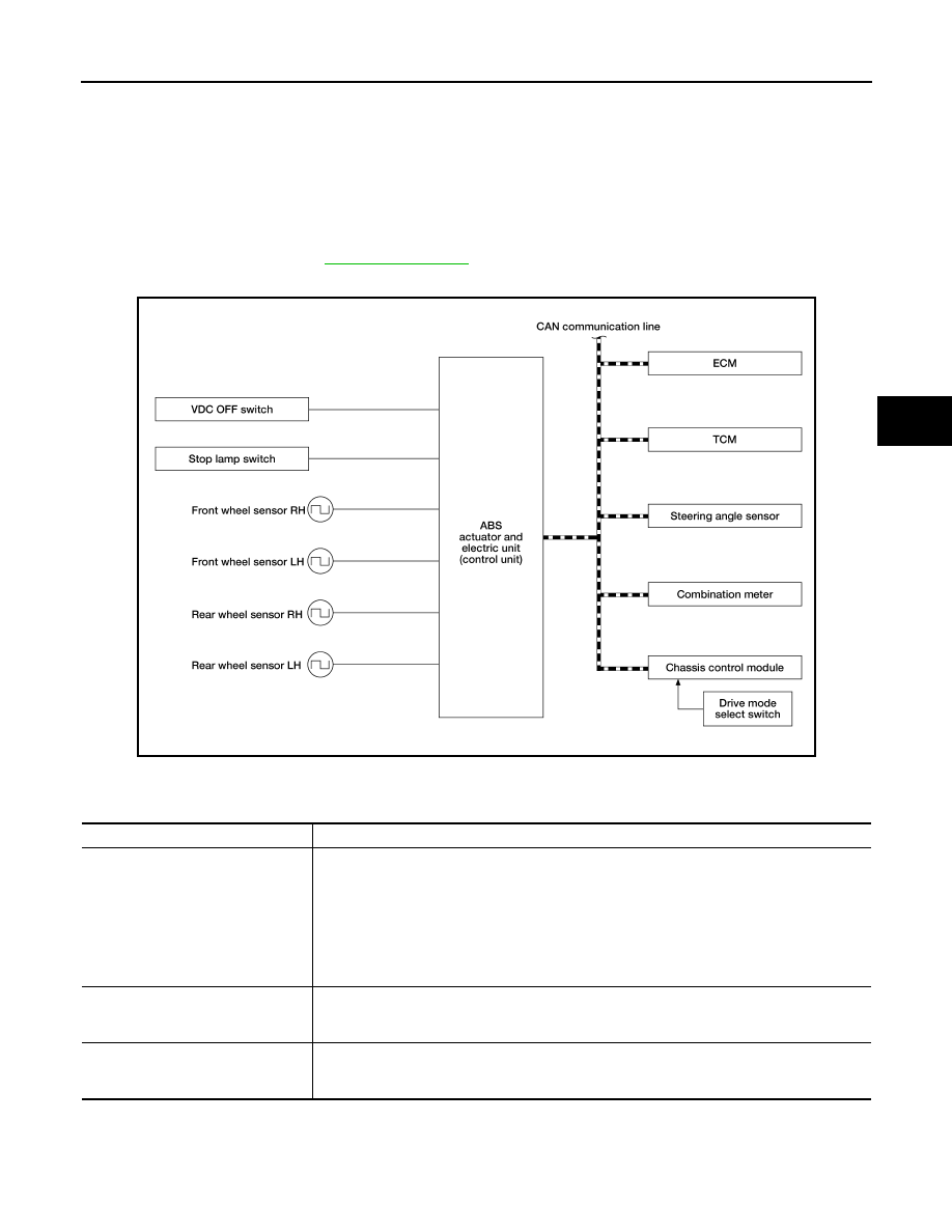
SYSTEM DIAGRAM
INPUT SIGNAL AND OUTPUT SIGNAL
Major signal transmission between each unit via communication lines is shown in the following table.
ALFIA0420GB
Component
Signal description
ECM
Mainly transmits the following signals to ABS actuator and electric unit (control unit) via CAN
communication.
• Accelerator pedal position signal
• Engine speed signal
• Engine torque signal
Mainly receives the following signals from ABS actuator and electric unit (control unit) via CAN
communication.
• Engine torque request signal
TCM
Mainly transmits the following signals to ABS actuator and electric unit (control unit) via CAN
communication.
• Current gear position signal
Chassis control module
Mainly transmits the following signals to ABS actuator and electric unit (control unit) via CAN
communication.
• Active trace control signal