Nissan Qashqai J11. Manual - part 817


  Index      Nissan     Nissan Qashqai J11 - Service and Repair Manual


Search            


Content   ..  815  816  817  818   ..


Nissan Qashqai J11. Manual - part 817


DLN-184

< SYMPTOM DIAGNOSIS >

[REAR PROPELLER SHAFT: C-CVJ-C]

NOISE, VIBRATION AND HARSHNESS (NVH) TROUBLESHOOTING

SYMPTOM DIAGNOSIS

NOISE, VIBRATION AND HARSHNESS (NVH) TROUBLESHOOTING

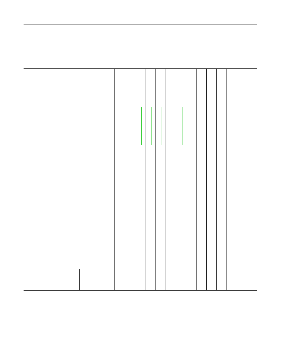
NVH Troubleshooting Chart

INFOID:0000000010763744

Use the chart below to find the cause of the symptom. If necessary, repair or replace these parts.

×

: Applicable

Reference

DL

N-18

5,

 "I

ns

pe

ct

io

n"

DL

N-18

6,

 "Exp

lo

de

d V

ie

w

"

DL

N-18

5,

 "I

ns

pe

ct

io

n"

DL

N-18

9,

 "I

ns

pe

ct

io

n"

DL

N-18

5,

 "I

ns

pe

ct

io

n"

DL

N-18

5,

 "I

ns

pe

ct

io

n"

DL

N-18

5,

 "I

ns

pe

ct

io

n"

NVH of REAR FINAL 

DR

IVE in this section.

NVH in F

AX, RAX

, FS

U,

 an

d RS

se

ct

ion

.

NVH in WT

 se

ct

io

n.

NVH in WT

 se

ct

io

n.

NVH in F

AX and RAX section.

NVH in BR section.

NVH in ST 

section.

Possible cause and SUSPECTED PARTS

Un

ev

en

 rot

a

ti

ng

 to

rq

ue

Ce

nt

e

r be

ari

n

g

 im

pro

p

e

in

st

al

la

ti

on

Exc

e

s

s

ive

 c

e

n

ter 

be

arin

ax

ia

l e

n

d

 pl

ay

Ce

nt

e

r be

ari

n

g

 mou

n

ti

n

g

 (in

s

u

lat

or) c

rack

s

, da

ma

ge

 or de

te

ri

ora

tio

n

Ex

ce

ssi

v

e

 jo

in

t an

gl

e

Ro

ta

ti

on

 i

m

ba

la

nc

e

Ex

ce

ssi

v

e

 run

o

u

t

DIFFERENTIAL

AXLE

 AND SUSPE

N

S

ION

TIRE

ROA

D

 WHEEL

DR

IVE SHAF

T

BRAKE

STEERING

Symptom

Noise

×

×

×

×

×

×

×

×

×

×

×

×

×

×

Shake

×

×

×

×

×

×

×

×

Vibration

×

×

×

×

×

×

×

×

×

×

×

REAR PROPELLER SHAFT

DLN-185

< PERIODIC MAINTENANCE >

[REAR PROPELLER SHAFT: C-CVJ-C]

C

E

F

G

H

I

J

K

L

M

A

B

DLN

N

O

P

PERIODIC MAINTENANCE

REAR PROPELLER SHAFT

Inspection

INFOID:0000000010763745

LOOSENESS OF CONNECTED PART

Check each fixing bolt and nut for looseness using torque wrench. For each tightening torque, refer to 

DLN-

186, "Exploded View"

.

BACKLASH OF JOINT PART

Move the joint of propeller shaft up and down and from side to side
(axial direction of shaft and right angle to shaft) to check that the joint
has no backlash. If the joint has a malfunction, remove propeller
shaft and perform inspection.

BACKLASH OF CENTER BEARING

Move the shaft near center bearing up and down and from side to
side (axial direction of shaft and right angle to shaft) to check that the
bearing has no backlash. If the bearing has a malfunction, remove
propeller shaft and perform inspection.

APPEARANCE AND NOISE

• Check the propeller shaft tube surface for dents or cracks. If malfunction is detected, replace propeller shaft

assembly.

• If center bearing is noisy or damaged, replace propeller shaft assembly.

VIBRATION

If vibration is present at high speed, adjust the propeller shaft phase first.
1.

Check the propeller shaft for bend and damage. If damaged, replace propeller shaft assembly.

2.

Perform a cruise test drive to check the propeller shaft for runout. If vibration occurs, separate propeller
shaft at final drive companion flange; then change the phase between electric controlled coupling stud bolt
and propeller shaft by the one bolt hole at a time and install propeller shaft.

3.

If vibration is still detected, measure propeller shaft runout after removing it. Refer to 

DLN-189, "Inspec-

tion"

.

MAA0555D

MAA0005D

DLN-186

< REMOVAL AND INSTALLATION >

[REAR PROPELLER SHAFT: C-CVJ-C]

REAR PROPELLER SHAFT

REMOVAL AND INSTALLATION

REAR PROPELLER SHAFT

Exploded View

INFOID:0000000010763746

Removal and Installation

INFOID:0000000010763747

REMOVAL

1.

Shift transaxle to the neutral position, and then release parking brake.

2.

Remove mounting rubber 

 of main muffler. Refer to 

EX-11,

"Removal and Installation"

 (MR20DD), 

EX-22, "Removal and

Installation"

 (R9M).

CAUTION:

Remove only near the center bearing mounting bracket of
propeller shaft.

Center bearing mounting bracket 
(upper)

Clip

Propeller shaft assembly

Center bearing mounting bracket 
(lower)

: Vehicle front

: N·m (kg-m, ft-lb)

: Always replace after every disassembly.

JSDIA5323GB

JSDIA5464ZZ

REAR PROPELLER SHAFT

DLN-187

< REMOVAL AND INSTALLATION >

[REAR PROPELLER SHAFT: C-CVJ-C]

C

E

F

G

H

I

J

K

L

M

A

B

DLN

N

O

P

3.

Remove heat insulator 

.

4.

Put matching marks 

 on propeller shaft flange yoke and trans-

fer companion flange.

CAUTION:

For matching mark, use paint. Never damage propeller shaft
flange yoke and transfer companion flange. 

5.

Put matching marks 

 on propeller shaft flange yoke and elec-

tric controlled coupling.

CAUTION:

• For matching mark, use paint. Never damage propeller

shaft flange yoke and electric controlled coupling. 

• If the tip of stud bolt of electric controlled coupling has a

paint mark, place a matching mark for identification of the
position of applicable stud bolt.

6.

Loosen mounting nuts of center bearing mounting bracket.
NOTE:
Tighten mounting nuts temporarily to prevent drop of propeller
shaft.

7.

Remove propeller shaft assembly fixing bolts, and separate pro-
peller shaft assembly from transfer companion flange.

JSDIA5324ZZ

JSDIA5328ZZ

JSDIA5325ZZ

JSDIA5326ZZ

JSDIA5329ZZ


Content   ..  815  816  817  818   ..