Nissan Qashqai J11. Manual - part 658
SERVICE DATA AND SPECIFICATIONS (SDS)
TM-207
< SERVICE DATA AND SPECIFICATIONS (SDS)
[6MT: RS6F52A]
C
E
F
G
H
I
J
K
L
M
A
B
TM
N
O
P
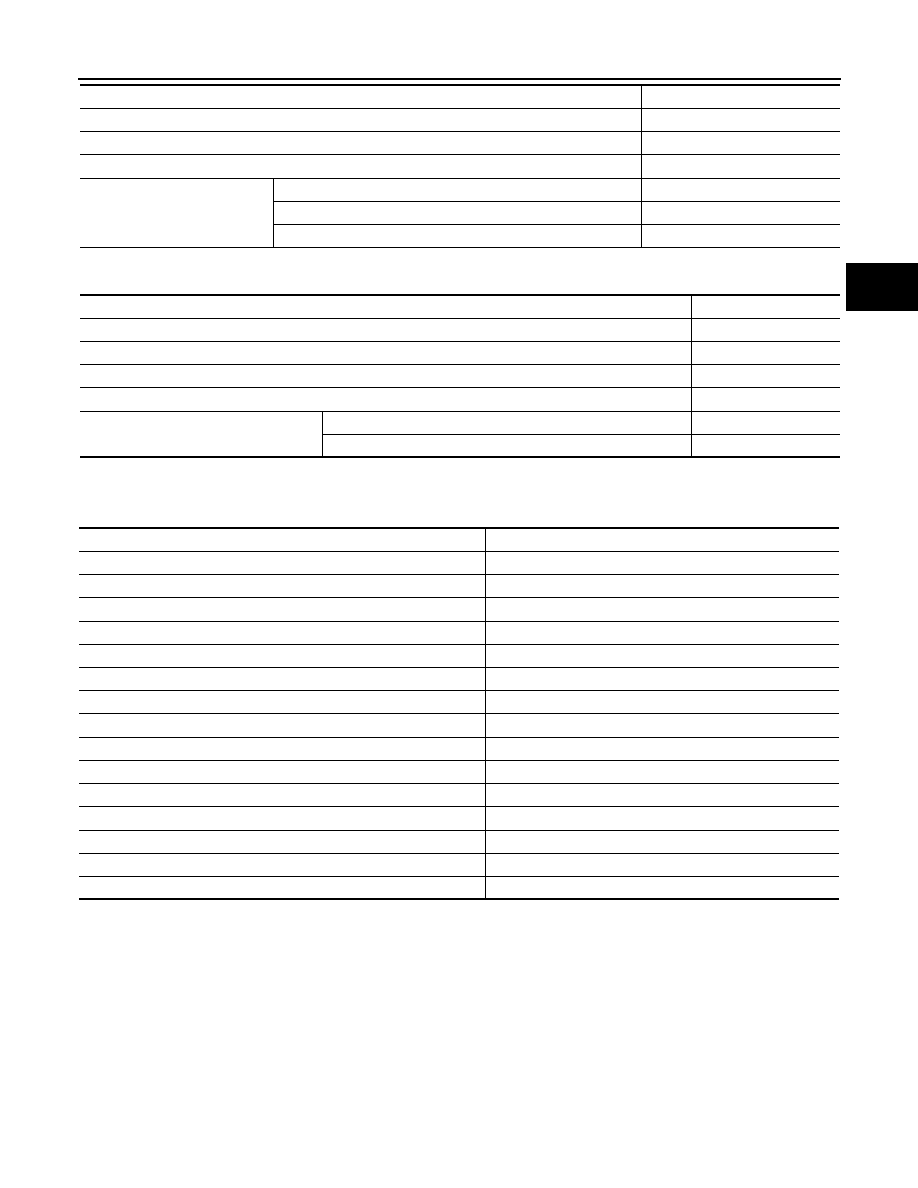
FINAL GEAR
End Play
INFOID:0000000010288544
Unit: mm (in)
Baulk Ring Clearance
INFOID:0000000010288545
Remarks
Reverse synchronizer
Installed
Double-cone synchronizer
3rd
Triple-cone synchronizer
1st and 2nd
Engine type
R9M
Transaxle model
RS6F52A
Axle type
4WD
Model code number
JA60A
Engine type
R9M
Transaxle model
RS6F52A
Axle type
4WD
Model code number
JA60A
Final gear ratio
4.266
Number of teeth
Final gear/Pinion
64/15
Side gear/Pinion mate gear
14/10
Items
Standard value
1st main gear
0.20 - 0.30 (0.0079 - 0.0118)
2nd main gear
0.06 - 0.16 (0.0024 - 0.0063)
6th main gear
0 - 0.1 (0 - 0.004)
3rd input gear
0.18 - 0.31 (0.0071 - 0.0122)
4th input gear
0.20 - 0.30 (0.0079 - 0.0118)
5th input gear
0.06 - 0.16 (0.0024 - 0.0063)
6th input gear
0.06 - 0.16 (0.0024 - 0.0063)
Reverse idler gear
0.04 - 0.10 (0.0016 - 0.0039)
6th input gear bushing
0 - 0.1 (0 - 0.004)
Input shaft
0 - 0.06 (0 - 0.0024)
Mainshaft
0 - 0.06 (0 - 0.0024)
Mainshaft C-ring
0 - 0.06 (0 - 0.0024)
Striking rod
0.05 - 0.152 (0.0020 - 0.0060)
Output gear bearing (For 4WD)
0 - 0.06 (0 - 0.0024)
Output gear assembly (For 4WD)
0 - 0.06 (0 - 0.0024)