Nissan Qashqai J11. Manual - part 647
TRANSAXLE ASSEMBLY
TM-163
< UNIT DISASSEMBLY AND ASSEMBLY >
[6MT: RS6F52A]
C
E
F
G
H
I
J
K
L
M
A
B
TM
N
O
P
3.
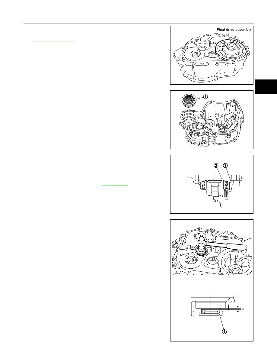
Install final drive assembly into clutch housing.
4.
Select differential side bearing adjusting shim. Refer to
CAUTION:
Never select differential side bearing adjusting shim with
output gear assembly installed on clutch housing.
5.
Remove final drive assembly.
6.
Turn clutch housing upside down as shown in the figure. And
then install output gear assembly (1) into clutch housing.
CAUTION:
• Gently install it, aligning the clutch housing hole with the
center of output gear assembly.
• Install output gear assembly, straightening it with a mag-
net.
• Never damage clutch housing and output gear assembly.
7.
Install snap ring (1) onto clutch housing and make sure that end
play (gap between snap ring and groove) of output gear assem-
bly (2) satisfies the standard value.
CAUTION:
• Only one snap ring can be selected.
• Never reuse snap ring.
• Never damage clutch housing.
8.
Install input shaft oil seal (1) to clutch housing using the drift (A)
[SST: ST35321000].
CAUTION:
• Never reuse input shaft oil seal.
• When installing, never incline input shaft oil seal.
• Never damage clutch housing.
SCIA0888E
JPDIC0074ZZ
End play standard value
“L”
: Refer to
.
JPDIC0043ZZ
Dimension “H”
: 1.1 - 2.1 mm (0.043 - 0.083 in)
PCIB1814E