Nissan Qashqai J11. Manual - part 643
AIR BREATHER HOSE
TM-147
< REMOVAL AND INSTALLATION >
[6MT: RS6F52A]
C
E
F
G
H
I
J
K
L
M
A
B
TM
N
O
P
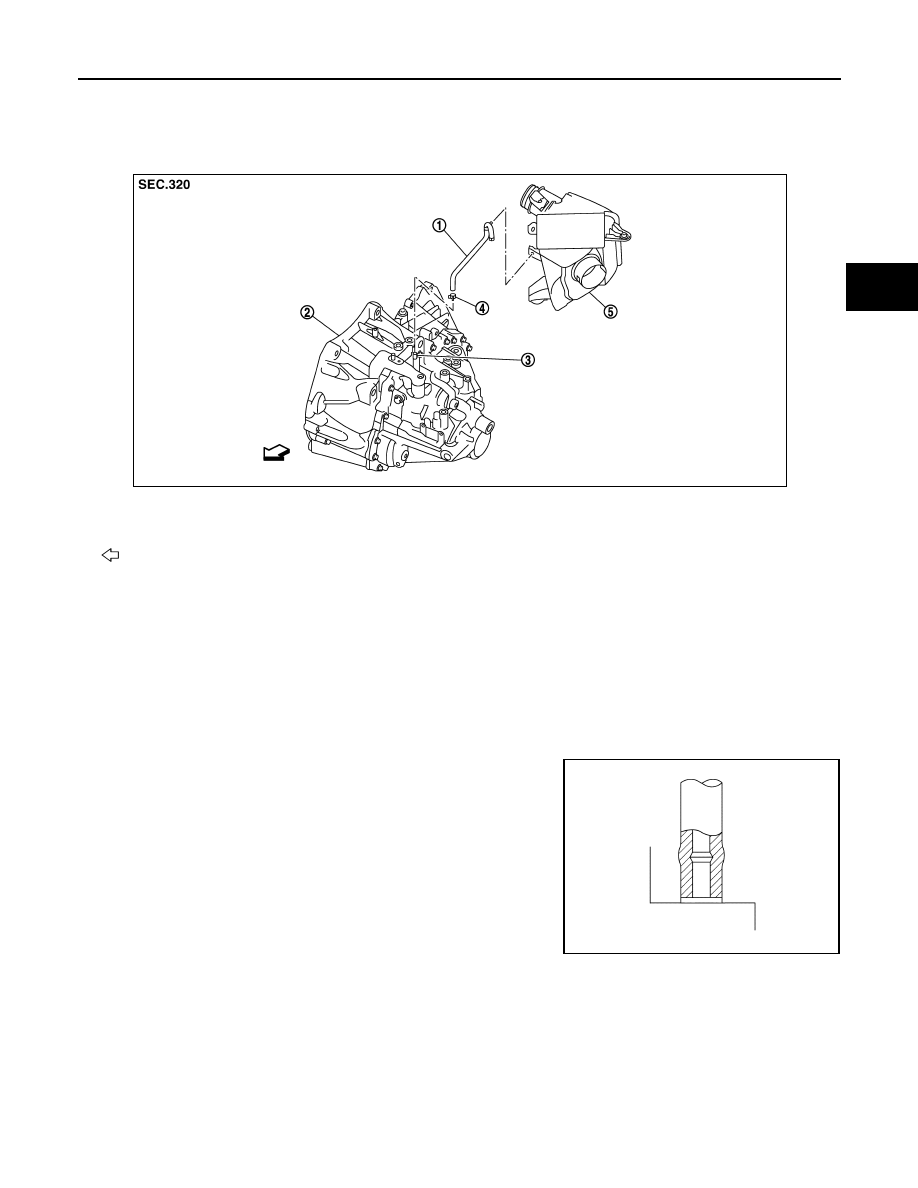
AIR BREATHER HOSE
Exploded View
INFOID:0000000010288507
Removal and Installation
INFOID:0000000010288508
REMOVAL
Refer to the figure for removal procedure.
INSTALLATION
Refer to the figure for installation procedure.
CAUTION:
• Make sure there are no pinched or restricted areas on the air breather hose caused by bending or
winding when installing it.
• Be sure to insert air breather hose into air breather tube until
hose end reaches the tube's base.
• Set air breather hose with painted mark facing forward.
• Install air breather hose to air cleaner case by fully inserting
the clip.
1.
Air breather hose
2.
Transaxle assembly
3.
Air breather tube
4.
Clamp
5.
Air cleaner case
: Vehicle front
JPDIC0051ZZ
SCIA2663J