Nissan Qashqai J11. Manual - part 2226


  Index      Nissan     Nissan Qashqai J11 - Service and Repair Manual


Search            


Content   ..  2224  2225  2226  2227   ..


Nissan Qashqai J11. Manual - part 2226


DAS-318

< SYSTEM DESCRIPTION >

[PARK ASSIST]

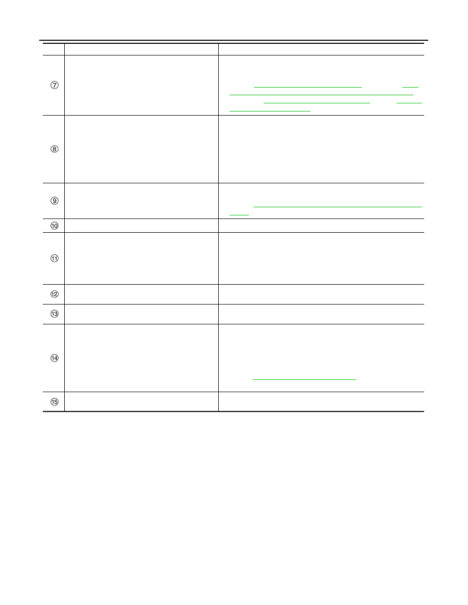
COMPONENT PARTS

ECM

• When Around View Monitor with park assist operates, an idling stop 

prohibited signal is received from the EPS control unit and idling stop 
is not performed.

• Refer to 

ECH-12, "Component Parts Location"

 (HRA2DDT), 

ECM-

14, "ENGINE CONTROL SYSTEM : Component Parts Location"


(MR20DD), 

ECK-12, "Component Parts Location"

 (K9K) or 

EC9-12, 

"Component Parts Location"

 (R9M) for detailed installation location.

EPS control unit

• EPS control unit performs Around View Monitor with park assist con-

trol by receiving the Around View Monitor with park assist status sig-
nal for switching from normal operation to parking assist mode, and 
the steering angle command signal for steering operation from the 
Around View Monitor control unit via CAN communication.

• During Around View Monitor with park assist, the stop/start system 

prohibited signal is transmitted to ECM via CAN communication so 
that stop/start is not performed.

BCM

• Turn signal switch signal is transmitted to the Around View Monitor 

control unit via CAN communication.

• Refer to 

BCS-7, "BODY CONTROL SYSTEM : Component Parts Lo-

cation"

 for detailed installation location.

Side camera LH

• The side camera LH is installed in the door mirror LH.

Rear view camera

• Rear view camera washer control unit is installed under the luggage 

rear plate.

• Communicates with around view monitor control unit via serial com-

munication line.

•  Activates air pump and washer pump according to the signal from 

Around View Monitor control unit.

Sonar buzzer

• A buzzer sounds according to operation signal from the sonar con-

trol unit.

Steering angle sensor

• Steering angle signal is transmitted to the Around View Monitor con-

trol unit via CAN communication.

NAVI control unit

• The NAVI control unit performs display of all lines of Around View 

Monitor with park assist plotted by the Around View Monitor control 
unit, all switch displays of Around View Monitor with park assist, dis-
play of guidance messages, and voice guidance.

• Camera switch signal and parking assist signal, etc. are transmitted 

to the Around View Monitor control unit via CAN communication.

• Refer to 

AV-128, "Component Parts Location"

 for detailed installation 

location.

Sonar control unit

Sonar control unit controls Around View Monitor with park assist (par-
allel parking mode).

No.

Component parts

Function

DAS

SYSTEM

DAS-319

< SYSTEM DESCRIPTION >

[PARK ASSIST]

C

D

E

F

G

H

I

J

K

L

M

B

N

P

A

SYSTEM

System Description

INFOID:0000000010451331

SYSTEM DIAGRAM

INPUT/OUTPUT SIGNAL ITEM

Input Signal Item

Output Signal Item

JMOIA0029GB

Transmit unit

Signal name

Description

EPS control unit

CAN commu-
nication

IPA permit signal

Receives confirmation that Around View Monitor with 
park assist can operate.

EPS torque signal

Receives the steering input torque.

Steering angle 
sensor

CAN commu-
nication

Steering angle sensor signal

Receives the amount of rotation, angular velocity, and ro-
tational direction of the steering wheel.

ABS actuator 
and electric unit 
(control unit)

CAN commu-
nication

Vehicle speed signal (ABS)

Receives the wheel speed of the four wheels.

VDC operation signal

Receives the VDC operation status.

VDC malfunction signal

Receives the VDC malfunction status.

TCM

CAN commu-
nication

CVT malfunction signal

Receives the CVT malfunction status.

Shift position signal

Receives the selector lever position.

BCM

CAN commu-
nication

Turn signal switch signal

Receives the turn signal switch position.

ECM

CAN commu-
nication

ECM malfunction signal

Receives the ECM malfunction status.

NAVI control 
unit

ITS communi-
cation

IPA switch signal

Receives the Around View Monitor with park assist switch 
status.

Sonar control 
unit

CAN commu-
nication

Sonar indicator signal

Receives the distance to the obstacle detected by the so-
nar sensor.

DAS-320

< SYSTEM DESCRIPTION >

[PARK ASSIST]

SYSTEM

DESCRIPTION

• Around View Monitor with park assist is a function in which the system operates the steering wheel to assist

the steering operation of the driver when performing parallel parking or entering a garage.

CAUTION:

Around View Monitor with park assist does not have a function for avoiding obstacles automatically.
When driver operates the vehicle, caution should always be paid to the surroundings visually.

• When the system is operating, at the same time that the conditions surrounding the vehicle are displayed on

the Around View Monitor, display of the predicted course lines and turning guidance box, etc. is performed.

Perpendicular parking

Reception unit

Signal name

Description

EPS control unit

CAN commu-
nication

Steering angle command signal

Transmits signal and steers the steering wheel.

IPA operation signal

Transmits the Around View Monitor with park assist oper-
ation status.

IPA malfunction signal

Transmits the Around View Monitor with park assist mal-
function status.

NAVI control 
unit

ITS communi-
cation

IPA switch display signal

Transmits signal and displays the Around View Monitor 
with park assist switch.

Guidance audio output signal

Transmits signal and outputs the Around View Monitor 
with park assist audio.

Sonar control 
unit

CAN commu-
nication

Buzzer signal

Transmits signals and outputs the Around View Monitor 
with park assist buzzer sound.

ITS communi-
cation

JMOIA0048GB

DAS

SYSTEM

DAS-321

< SYSTEM DESCRIPTION >

[PARK ASSIST]

C

D

E

F

G

H

I

J

K

L

M

B

N

P

A

Parallel parking

At parking box setting

When driving forward

When reversing (when the 
turning box is detected)

When reversing (when the target park-
ing box is detected)

No.

Line name

Line color

Function

Predicted course lines

Forward: green
Reverse: orange

Displays the course for driving the ve-
hicle within the target parking box

Obstacle guidance lines

Red

Displays parking space guidance

Parking guide box

Blue

Displays the desired parking position

Steering cut back guide box

Green

Displays the position for starting re-
versing or steering cut back

JMOIA0074GB

At parking box setting

When driving forward

When reversing (when the 
turning box is detected)

When reversing (when the target park-
ing box is detected)

No.

Line name

Line color

Function

Predicted course lines

Forward: green
Reverse: orange

Displays the course for driving the ve-
hicle within the target parking box

Parking space detection

Red

Displays the parking space detection


Content   ..  2224  2225  2226  2227   ..