Nissan Qashqai J11. Manual - part 2225


  Index      Nissan     Nissan Qashqai J11 - Service and Repair Manual


Search            


Content   ..  2223  2224  2225  2226   ..


Nissan Qashqai J11. Manual - part 2225


DAS-314

< PRECAUTION >

[PARK ASSIST]

PRECAUTIONS

2.

Turn key switch to the OFF position with the driver side door opened.

3.

Get out of the vehicle and close the driver side door.

4.

Wait at least 3 minutes. For vehicle with the engine listed below, remove the battery terminal after a lapse
of the specified time.

CAUTION:

While waiting, never operate the vehicle such as locking, opening, and closing doors. Violation of
this caution results in the activation of ACC power supply according to the Auto ACC function.

5.

Remove 12V battery terminal.

CAUTION:

After installing 12V battery, always check self-diagnosis results of all ECUs and erase DTC.

INSTRUCTION 2 (FOR VEHICLES PARKED BY IGNITION SWITCH OFF)

1.

Unlock the door with intelligent key or remote keyless entry.
NOTE:
At this moment, ACC power is supplied.

2.

Open the driver side door.

3.

Open the hood.

4.

Close the driver side door.

5.

Wait at least 3 minutes.

CAUTION:

While waiting, never operate the vehicle such as locking, opening, and closing doors. Violation of
this caution results in the activation of ACC power supply according to the Auto ACC function.

6.

Remove 12V battery terminal.

CAUTION:

After installing 12V battery, always check self-diagnosis results of all ECUs and erase DTC.

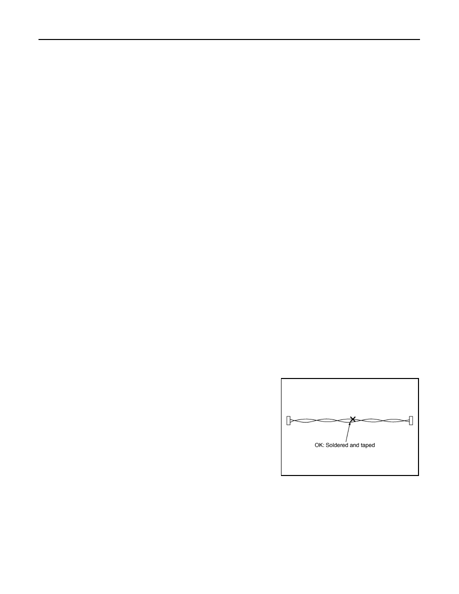
Precautions For Harness Repair

INFOID:0000000010464123

ITS communication uses a twisted pair line. Be careful when repairing it. 
• Solder the repaired area and wrap tape around the soldered area. 

NOTE:
A fray of twisted lines must be within 110 mm (4.33 in).

D4D engine

: 20 minutes

HRA2DDT

: 12 minutes

K9K engine

: 4 minutes

M9R engine

: 4 minutes

R9M engine

: 4 minutes

V9X engine

: 4 minutes

SKIB8766E

DAS

PRECAUTIONS

DAS-315

< PRECAUTION >

[PARK ASSIST]

C

D

E

F

G

H

I

J

K

L

M

B

N

P

A

• Bypass connection is never allowed at the repaired area.

NOTE:
Bypass connection may cause ITS communication error. The
spliced wire becomes separated and the characteristics of twisted
line are lost.

SKIB8767E

DAS-316

< SYSTEM DESCRIPTION >

[PARK ASSIST]

DESCRIPTION

SYSTEM DESCRIPTION

DESCRIPTION

Description

INFOID:0000000010451327

• Around View Monitor with park assist that supports driving operation when parking is adopted.
• Around View Monitor with park assist is a function in which the system operates the steering wheel to assist

the steering operations of the driver when performing parallel parking or entering a garage.

• When the target parking position is set on the Around View Monitor, the conditions surrounding the vehicle,

the predicted course lines, and the turning guidance box, etc. are shown on the monitor, and while assisting
the drivers steering wheel operations, the system provides driving operation guidance so that the vehicle is
parked close to the set parking guidance box.

• In parallel parking mode, the parking space is detected by ultrasound waves, and the driver is notified. When

the driver performs Parking Assist start operation, the system assists steering wheel operation while guiding
driving operation, for parking maneuvers performed near the parking space.

DAS

COMPONENT PARTS

DAS-317

< SYSTEM DESCRIPTION >

[PARK ASSIST]

C

D

E

F

G

H

I

J

K

L

M

B

N

P

A

COMPONENT PARTS

Component Parts Location

INFOID:0000000010451328

No.

Component parts

Function

Front camera

• Front camera is located above the inside mirror and detect the lane 

marker in travel lane.

• Transmits lane marker signal to Around View Monitor unit via CAN 

communication.

Side camera RH

• The side camera RH is installed in the door mirror RH.

Sonar control unit

• Sonar control unit controls Around View Monitor with park assist 

(parallel parking mode).

• While Around View Monitor with park assist is operating, when the 

system wants to recommend an operation to the driver, and when 
the system is canceled, a buzzer sounds due to a sonar output re-
quest from the Around View Monitor. 

• Refer  to 

SN-58, "Component Parts Location"

 for detailed installation 

location.

Around view monitor control unit

• Around View Monitor control unit controls Around View Monitor with 

park assist.

• Around View Monitor control unit is located at the back of the glove 

box.

• Each ECU transmits and receives the required signals via CAN com-

munication or ITS communication.

• Power is supplied to each camera by turning the ignition switch ON.
• The camera image signal received from each camera is converted 

and compounded inside the Around View Monitor control unit and 
transmitted to the NAVI control unit.

ABS actuator and electric unit (control unit)

• Wheel rotation sensor signal and the operation statuses of the VDC, 

TCS and ABS systems, etc. are transmitted to the Around View Mon-
itor control unit via CAN communication.

• Refer  to 

BRC-8, "Component Parts Location"

 for detailed installation 

location.

TCM

• CVT control related signal is transmitted to Around View Monitor 

control unit via CAN communication.

• Refer  to 

TM-217, "CVT CONTROL SYSTEM : Component Parts Lo-

cation"

 (RE0F10D) or 

TM-430, "CVT CONTROL SYSTEM : Compo-

nent Parts Location"

 (RE0F10G) for detailed installation location.

JMOIA0054ZZ


Content   ..  2223  2224  2225  2226   ..